Review Article | | Peer-Reviewed

Design of Semi-rigid Pavements for Super-heavy Load Movements: Review and Evaluation of Critical Design Parameters

Received: 2 July 2026     Accepted: 20 July 2026     Published: 30 July 2026
Views:       Downloads:
Abstract

This study examines the effects of super-heavy (SHL) vehicles on semi-rigid flexible pavements using various pavement design methodologies. At present, no standardised framework exists for the design of semi-rigid flexible pavements subjected to SHL movements. Current practice commonly relies on performance models originally developed for conventional heavy vehicles; however, the applicability of these models to SHL conditions remains questionable and may result in significant underestimation of pavement damage. In this study, critical pavement responses are simulated mechanistically using the commercially available Mechanistic-Empirical pavement design software HIPAVE, following a benchmarking process against the FAARFIELD program. A hybrid set of pavement materials failure criteria is incorporated into the HIPAVE to simulate pavement responses under SHL operations. The simulation results obtained from HIPAVE show good agreement with those generated by FAARFIELD, demonstrating a reliability of the adopted modelling approach. Furthermore, a novel approach based on the concept of a representative SHL nucleus is proposed to characterise super-heavy loading configurations, enabling efficient assessment of pavement impacts while significantly reducing computational time. The findings from the literature review and numerical analyses indicate that further research is required to establish unified design guidelines and long-term field monitoring including the development of a simplified design chart or nomograph for semi-rigid flexible pavements subjected to SHL movements.

Published in American Journal of Civil Engineering (Volume 14, Issue 4)
DOI 10.11648/j.ajce.20261404.14
Page(s) 253-272
Creative Commons

This is an Open Access article, distributed under the terms of the Creative Commons Attribution 4.0 International License (http://creativecommons.org/licenses/by/4.0/), which permits unrestricted use, distribution and reproduction in any medium or format, provided the original work is properly cited.

Copyright

Copyright © The Author(s), 2026. Published by Science Publishing Group

Keywords

Super-heavy Load, Semi-rigid Pavements, Material Failure Criteria, Representative Nucleus, Layered Elastic Theory

1. Introduction
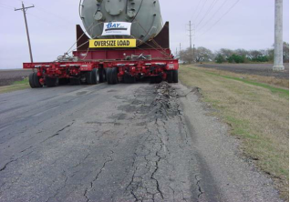
This study demonstrates the methodology of designing super-heavy load (SHL) movements on semi-rigid pavements using HIPAVE software. SHL vehicles are characterised by non-standard body configurations, low operating speeds, oversized dimensions, and gross vehicle weights (GVWs) that exceed statutory limits for axle and tyre loads. These vehicles typically have extreme gross weights ranging from 387 to 2819 tonnes, exceptionally high axle loads of 12-70 tonnes, and tyre loads of up to 17.5 tonnes . Their complex load arrangements often incorporate multiple wheel and axle assemblies, together with specially designed tyres operating at inflation pressures up to 2180 kPa . SHL movements frequently require specialised tailers and hauling units that are custom configured to accommodate the loads, resulting in non-standard and highly variable axle configurations. Consequently, the loading imposed by SHL movements is substantially greater than that experienced by conventional highway pavements. The resulting stress levels can induce excessive permanent deformations in the form of surface rutting and heaving as shown in Figure 1.
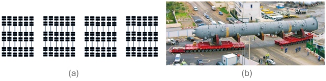
SHL vehicles are substantially larger and heavier than conventional heavy vehicles. Figure 2a and 2b show examples of a Louisiana-permitted SHL vehicle (LA-12T-16) and Cometto self-propelled modular transporter (SPMT), designated MSPE EV03 70T respectively.
Figure 1. Severe pavement damage on pavements by SHL movement .
Figure 2. (a) Louisiana permitted SHL vehicle LA-12T-16 with fragmental axle configuration axle spacing 1.4 m, spacing between trailers 5.33 and the vehicle width 11.56 m (b) Twin trailers SPMT front and rear .
At present, there is no standardised procedure for the design of semi-rigid pavements subjected to SHL movements. In this study, commercially available and accessible globally Mechanistic-Empirical pavement design software HIPAVE with an open system that can handle abnormal wheel loads and accommodates material properties and performance criteria is used to assess the critical pavement responses subject to SHL movements.
2. Literature Review
As part of MX missile programme, Barber and Ladd of the U.S Army Engineering Waterways Experiment Station conducted extensive full-scale pavement tests by adopting Corps of Engineers (CE) flexible pavement design criteria for SHL traffic. The study focused on a missile transporter weighing approximately 680 tonnes. The field-testing programme revealed that the predominant form of pavement distress was deep-seated consolidation caused by the exceptionally heavy loads applied through unusually large tyres.
Jooste and Fernando were commissioned by Texas Department of Transportation (TxDOT) to develop a methodology to evaluate the potential for pavement damage along proposed SHL routes including the identification of any temporary strengthening measures required to accommodate the load movements. They found that the proposed SHL route possessed adequate structural capacity and that modelling the load using an equivalent single-axle representation produced conservative estimates of potential for pavement damage.
Chen et al. demonstrated that tyre group loading exerts a substantially greater influence on pavement surface displacement and compressive strain at the top of the subgrade than single wheel representation. This infers that modelling wheel groups explicitly provides a more realistic representation of pavement response and is therefore preferable for SHL simulations. In the subsequent study, Chen et al. presented a case study involving the transportation of 1800-tonne super-heavy load over a flexible pavement in Louisiana. The pavement response was analysed using both with the three-dimensional finite element modelling based on the Mohr-Coulomb yield criterion and the BISAR layered elastic analysis program. Pavement performance was evaluated using the fatigue cracking and rutting criteria proposed by the Asphalt Institute .
Nimeri introduced the concept of the SHL Representative Nucleus, which was subsequently adopted and further developed by Hajj et al. . The Representative Nucleus is defined as a standardised loading configuration consisting of a 5 by 5 tyre cluster that produces the maximum vertical stress within the pavement structure under SHL conditions. The underlying premise is that the influence of tyres located beyond this critical loading zone becomes negligible. Consequently, the Representative Nucleus provides an efficient means of capturing the critical wheel-wheel and wheel-axle interaction effects without the need to explicitly model the entire vehicle configuration. The SuperPACK software was developed using this concept to facilitate the assessment of SHL movements on flexible pavements.
Skaff undertook a comprehensive verification and refinement of SuperPACK software and subsequently applied the enhanced methodology to a series of case studies involving the risk assessment of SHL movements on flexible pavements.
Khanal et al. used finite element method (FEM) to evaluate pavement layer stresses and strains under SHL movements during spring and winter conditions. Their analysis revealed that, despite movements involving approximately 55% less gross vehicle weight than winter movements, they resulted in nearly three times greater pavement damage.
Vandenbossche et al. were commissioned by the Pennsylvania Department of Transportation to develop Excel-based predictive models for quantifying the effects of SHL movements on flexible and rigid pavements; however, access to these workbooks remains restricted to users within the United States.
Perez-Gonzalez developed the i3C-SHL software, an analytical tool based on multi-layer elastic theory, to quantify the impact of SHL vehicles on pavements in Quebec. The software is calibrated to climatic conditions specific to the Quebec region, which constitutes one of its principal limitations, alongside restricted accessibility and limited applicability to conditions dissimilar to those found in Quebec.
Koh et al. developed methodologies to quantify superloads and assess their impacts on Iowa’s road infrastructure, encompassing jointed plain concrete pavements, flexible pavements and granular roads. This culminated in the development of the Road Infrastructure-Superload Analysis Tool (RISAT), which enables practitioners to evaluate structural damage and associated treatment costs induced by superload traffic.
3. Semi-rigid Flexible Pavements
A semi-rigid pavement typically comprises an asphalt surfacing layer constructed over cement-treated base (CTB), which is in turn supported by a granular subbase material. Within this configuration, the CTB layer contributes a substantial proportion of the overall load-carrying capacity of the pavement structure, owing to its relatively high stiffness and flexural strength compared with conventional unbound granular materials. This composite arrangement allows semi-rigid pavements to combine the surface performance characteristics of flexible pavements, such as smoothness and ease of maintenance, with the superior load distribution and structural durability typically associated with rigid pavement systems. As a result, semi-rigid pavements are particularly well suited to heavily trafficked pavements.
4. Principles of Super-heavy Load Analysis
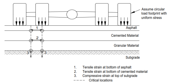
The determination of the induced pavement responses induced by surface wheel loads generated during SHL movements is essential for evaluating the structural adequacy of the pavement system. The critical strain locations considered within the pavement model are shown in Figure 3.
Figure 3. Pavement model for mechanistic-empirical procedure (Adapted from ).
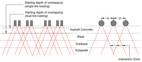
The stresses induced by SHL vehicle movements are expected to overlap significantly within the pavement structure, extending well beyond a certain depth. Assuming that the stress distribution from an individual wheel or axle load dissipates uniformly with depth, the influence of adjacent wheels or axles is generally considered negligible until the depth reaches one-half the spacing between the representative wheels or axles . Furthermore, the extent of stress overlap is governed by several factors, including the magnitude of surface load, wheel load configuration, pavement layer thicknesses, and the mechanical properties of the pavement materials, as illustrated in Figure 4 .
Figure 4. Concept of wheel load stress overlap and superposition principle (a) transverse direction (b) direction of travel (Adapted from ).
5. Pavement Modelling for Super-heavy Load
To address the absence of a comprehensive framework for assessing SHL movements on flexible pavements, Hajj et al. developed a mechanistic-based analysis methodology. This unified approach provides a systematic and reliable means of evaluating the structural impacts of SHL vehicles and led to the development of the SuperPACK software in the United States. While the methodology offers greater confidence in the timely assessment of SHL movements and addresses many of the unique challenges associated with super-heavy load transport, its application outside the United States remains limited. This is primarily because the methodology was developed and calibrated for pavement conditions, design practices, and loading environments specific to the United States. Furthermore, access to the SuperPACK software is restricted, which further constrains its adoption and implementation in other countries.
5.1. Nucleus of SHL Design Vehicle
The conventional approach to SHL pavement analysis involves modelling the complete tyre footprint of the design vehicle. To improve modelling efficiency, Nimeri et al. proposed an innovative methodology based on identifying a nucleus segment within the overall SHL tyre configuration. The underlying premise is that the loading effects generated by this nucleus segment can adequately replicate the critical pavement responses induced by the entire SHL vehicle.
The first step in identifying the nucleus segment of an SHL configuration is to determine the number of line loads (axle groups) in the longitudinal direction of travel and the spacing required between them for their interactions to become negligible in terms of induced pavement responses. For each analysis, the equivalent design traffic loading is used to replicate the loading conditions generated by the entire SHL vehicle. The second step involves evaluating the influence of wheel loads in the transverse direction on pavement responses. This is achieved by incrementally increasing the number of wheel loads included in the analysis until the addition of another tyre results in a negligible change in the induced pavement response at the critical location. The final step is to assess the effect of trailer spacing on pavement responses in the transverse direction.
5.2. Materials Characterisation
Proper characterisation of pavement layer materials is critical for the accurate simulation of load-pavement interactions and for predicting pavement responses that are representative of in-service field conditions.
5.2.1. Unbound Granular Materials
The stress-dependent behaviour of unbound base course and subbase layer is accounted for by using sub-layering method developed by Barker-Brabston of the U.S. Army Corps of Engineers (USACE). This approach characterises the resilient modulus (MR) of unbound materials as a function of the prevailing stress state within the pavement structure . Appropriate presumptive MR values for unbound pavement materials have been published by various agencies and may be adopted where project-specific laboratory data are unavailable .
5.2.2. Asphalt
Asphalt concrete (AC) is most appropriately characterised as a viscoelastic material whose behaviour is influenced by both loading frequency and temperature . Consequently, the slow-moving SHL vehicle plays a major role in the viscoelastic response of the AC layer, as reduced vehicle speeds increase load application times and alter the material response.
The viscoelastic behaviour of the AC layer is characterised by incorporating the dynamic modulus (E), which is a function of material temperature and loading frequency. An AC dynamic modulus master curve can be developed by conducting a series of E tests over a range of temperatures and loading frequencies. Alternatively, an appropriate presumptive E master curve published by asphalt suppliers or other recognised agencies may be adopted .
5.2.3. Cemented Materials
Unlike conventional concrete pavements, cemented materials can be regarded as low-grade concrete layers. They do not contain reinforcement or joints to mitigate stress development; instead, they rely on the tensile strength of the material and the frictional resistance provided by the underlying granular subbase to control shrinkage cracking . Due to their ability to enhance the strength and durability of granular materials at a relatively low cost, cemented materials have been widely adopted in pavement construction and remain an attractive option for pavement engineers .
5.2.4. Subgrade
The stiffness of the pavement foundation, characterised by the subgrade elastic modulus, is preferably determined through laboratory testing to ensure an accurate representation of field conditions. The maximum subgrade modulus of 150 MPa is generally adopted in pavement design practice. It should also be noted that the construction of semi-rigid pavements can be challenging on subgrades with a CBR of less than 5%. Conversely, for subgrades with higher strength, an in-situ CBR of at least 10% is typically required at the time of construction to ensure adequate compaction and performance of the cement-stabilised base layers .
5.3. Pavement Performance Models
Pavement structures are designed to ensure that these critical responses remain below tolerable limits throughout the design life, thereby maintaining the structural integrity and long-term performance. As of now, no widely accepted critical response parameter or performance criterion has been established for unbound granular layers.
Numerous pavement performance models have been developed by researchers to predict the long-term behaviour and deterioration of pavement structures under repeated traffic loading . In general, pavement performance models are represented by regression equations derived from experimental data and are commonly expressed as either a linear relationship on a log-log scale or a log-linear relationship. For cement-treated materials, European pavement design methodologies frequently employ log-linear performance models to relate the allowable number of load repetitions to the tensile strain at the bottom of the cement-treated layer, as expressed in Equation (1) .
Log10N=k-b|ε|(1)
where N is the allowable repetitions (predicted life), k is a material constant, b is the material damage exponent and ε is the induced strain (dimensionless). Generally, most performance models may be expressed as in Equation (2).
N=kεb(2)
These performance models are incorporated into mechanistic-empirical pavement design procedures in conjunction with layered elastic analysis.
5.3.1. Asphalt Failure Criteria
Asphalt failure models are commonly expressed in the form of power-law relationship, as represented in Equation (3). Most existing asphalt fatigue prediction models are primarily empirical in nature and have limitations in accurately representing actual field conditions, including rest periods between load applications, temperature variations, and the fatigue endurance limit behaviour of asphalt mixtures. These limitations have motivated the development of alternative approaches, such as the energy-based ratio of dissipated energy change (RDEC) concept proposed by Shen and Carpenter . The RDEC approach was subsequently adopted by FAA for implementation in FAARFIELD . Table 1 summarises the commonly accepted published asphalt fatigue failure criteria used in pavement design practice.
Table 1. Selected publications for asphalt failure criteria.

Study

Material constant (k)

Damage exponent (b)

Comments

Finn et al.

17721

3.3

For highway pavements and power curve fitted from log N = 15.947 - 3.291 log εt10-6 - 0.8541 logE103 where εt is asphalt tensile strain, E asphalt elastic modulus (psi)

PCASE

5136

5

Based UFC 3-260-02 for airfield pavements

. Assume E= 200000 psi (1380 MPa) and power curve fitted from N = 102.68-5logεt-2.665logE

Asphalt Institute (Chen et al.

)

19518

3.3

Power curve fitted from N = 0.0796 1εt3.2911E0.854developed by Asphalt Institute

successfully used by Chen et al. for SHL pavement analysis.

AfPA

5848

5

For ports and container terminal pavements. Assume E = 1380 MPa and power curve fitted from log N = RF x 5 xlog860 xlogNf200-1900με-2logE*+logERef+3.8 where Nf200 is number of cycles to failure tested at 20°C 10Hz and 200με, Eref is the measured modulus, E* is the test modulus of interest

Austroads

5986

5

For highway pavements. Assume DIT AC14 mix

with E=1196 MPa and power curve fitted from N = SFRF6918(0.856Vb+1.08) E0.36με5where SF is field shift factor, RF is reliability factor, Vb is asphalt bitumen volume (%), με is asphalt tensile strain (microstrain). Based on Shell Equation

FAARFIELD

670

5.7

For aircraft pavements. Assume E = 1380 MPa and power curve fitted from N = 0.4801 PV-0.9007 where PV = 44.422εt5.14 E5.396VP3.069GP-2.681 where VP is volumetric parameter, GP is the aggregate gradation parameter. Based on principles ratio of dissipated energy change approach developed by Shen and Carpenter

.

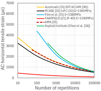
Figure 5. Comparison of asphalt failure criteria.
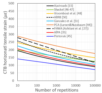
Figure 5 presents a comparison of the predicted asphalt horizontal tensile strain to failure using various published fatigue criteria. The results demonstrate a considerable variation in predicted performance among the different models. Notably, the FAARFIELD fatigue criterion consistently predicts the lowest allowable asphalt concrete horizontal tensile strain across all evaluated traffic loading cases, indicating a more conservative fatigue performance assessment compared with the other criteria.
When using the FAARFIELD program for airfield pavement design, the critical failure mode is generally influenced by subgrade strength and pavement material properties.
5.3.2. Cemented Material Failure Criteria
Currently, there is limited performance characterisation data for failure criteria of cemented materials applicable to the higher wheel loads associated with airfields, container terminals and industrial pavements. Based on research conducted by the Virginal Transportation Research Council for FHWA and Virginia Department of Transportation, the CTB modulus corresponding to the specified design strength range was reported to be between 4826 and 5516 MPa . Considering the inherent variability in CTB material properties, the FAA adopted a more conservative design modulus of 3447 MPa in FAARFIELD for P-304 cement-treated aggregate base course . It is noteworthy that current mechanistic-empirical pavement design procedures, including FAARFIELD, PCASE, and BPA, do not explicitly incorporate CTB fatigue failure criteria . In contrast, HIPAVE provides the capability to apply a fatigue performance criterion for CTB materials . AfPA validated the applicability of a single fatigue relationship for CTB materials based on a limited number of port terminal pavement case studies and concluded that a constant relationship may be suitable for design purposes.
The flexural fatigue behaviour of CTB materials is commonly characterised in term of strain ratio. The strain ratio is defined as the ratio of the allowable tensile strain to the tensile strain capacity of the material. The allowable tensile strain varies depending on CTB strength and typically ranges from approximately 125 to 300 microstrain (με), with higher-strength and higher-modulus CTB materials generally exhibiting lower allowable tensile strain values . Table 2 summarises the commonly used published CTB fatigue failure criteria applicable to pavement structures subjected to higher wheel loading conditions.
Figure 6. Comparison of CTB failure criteria.
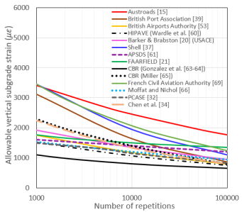
Table 2. Selected published CTB failure criteria.

Study

Material constant (k)

Damage exponent (b)

Comments

PCA

325.7

18.5

PCA method based on a curvature ratio approach. Use h = 6 in and Power curve fit from N0.028 = (R/Rc) x (1.05 - 0.042 x h) where R = CTB radius of curvature, Rc = critical R at failure of the beam (Rc = ≈7350 inches; h = fatigue beam thickness in inches)

Pretoruis

170.6

13.5

For pavement with CTB. Power curve fitted from strain ratio = ε/εb = 1 - 0.11 log N

Shackel

311

12

For roads and industrial pavements. Power curve fit from με = (993500 x fc) /E1.022 x N0.0502) where elastic modulus E = 57000√fc both E and fc (compressive strength) are in psi unit

Vroombout et al.

280

18

Proposed for aircraft concrete block paving. Based on laboratory accelerated loading facility trial results for CTB undertaken NAASRA

ARRB

311

12

For highway pavements

Gonzalez et al.

272

12

For highway pavements. Presumptive algorithms for in-service conditions based on ARRB formulation and laboratory tests

FHWA (Ashtiani et al.

)

361.6

10.5

Power curve fitted from In (N) = β1 x α1- εεbβ2 x α2 where β1 and β2 are field calibration factors, α1 and α2 are laboratory regression factors apply for virgin aggregates and for highway pavements

AfPA

250

12

Validated against limited port pavements data

Austroads

235

12

For highway pavements. k equal to 235 and 233 for CTB base and CTB subbase with flexural strength 1.4 and 1.2 MPa respectively

A comparative evaluation was conducted to assess the variability of these failure criteria, and the results are presented in Figure 6. The figure indicates that the CTB failure criterion proposed by Pretoruis predicts a tensile strain of approximately 70 με, below which the influence of traffic loading on fatigue life becomes negligible. This observation is consistent with the concept of a fatigue endurance limit for CTB materials, as proposed by Carpenter et al. .
5.3.3. Subgrade Failure Criteria
Apart from Austroads and Shell for highway loading conditions, the commonly used published subgrade failure criteria applicable to higher wheel loads used on airfields, container terminals and industrial pavements are listed in Table 3. It should be noted that the number of repetitions to subgrade failure is referred to coverage for aircraft pavements. Woodman , Rodway and Wardle and Rodway were based on full-scale pavement tests under heavy aircraft loadings up to 27 tonnes wheel loads conducted by the US Army Corps of Engineers. Interestingly, the empirical relationship developed for road models used in UK Road Note 29 is adopted in the British Ports Association (BPA) method , which incorporates the Nottingham University criterion . A comparison of subgrade failure criteria is presented in Figure 7. In general, all the failure criteria for aircraft and industrial pavements indicate lower strain values than those of highway pavements. This trend may be attributed to material characterisation adopted for difference methods used to design highways, aircrafts and industrial pavements.
Table 3. Selected published subgrade failure criteria.

Study

Material constant (k)

Damage exponent (b)

Comments

Shell

18000

4

Adopted in DESIGNPAVE CMAA software (Rahman et al.

) 95% reliability, based on AASHO road test

BPA

21600

3.57

Based on Brown and Brunton

, British conditions for UK Practice Road Note 29 and rut depth 20 mm.

Barker and Brabston

(USACE)

5525

6.527

50% reliability, aircraft test pavement

BAA (Woodman

)

5820

5.747

50% reliability, based on USACE aircraft test pavement (Turnbull et al.

)

HIPAVE (Wardle et al.

)

4276

6.635

50% reliability, based on USACE aircraft test pavement (Turnbull et al.

)

APSDS

2472

16.13

Power curve fitted from N = kεBbased on USACE CBR method (S77-1 Method (Pereira

)) calibrated with aircraft loading (Wardle et al. ).

k = 1.64x10-09E3 - 4.31x10-07E2 + 2.18X10-05E + 0.00289 B = -2.12x10-07E3 + 8.38x10-04E2 - 0.0274E + 9.57 ε = maximum vertical strain at the top of subgrade

PCASE

4712

6.58

Based USACE UFC 3-260-02 for airfield pavements

. Power curve fitted from N=10000AεB

where A=0.000247+0.000245logMR and B=0.0658MR0.559

MR is subgrade resilient modulus (psi). Limited literature on calibration/validation

CBR (Gonzalez et al.

)

3046

7.19

Power curve fitted from Log (β) = 1.7782+0.2397 Log(C)1+0.503 Log (C)

CBR Beta reformulation procedure with constant concentration factor for all test points to eliminates ESWL concept and the Alpha factor. Use for CBR airfield pavement design method.

C = coverage

CBR (Miller

)

10900

4.42

Power curve fitted from Log (β) = 1.5586+0.0886 Log(C)1+0.0778 Log (C)

Revised CBR Beta criteria using concentration factor as a function of CBR with a better fit to the test data. Plot curve is 85% reliability and for aircraft pavements C = coverage, σ = stress at the top of subgrade (psi), β = πσCBR

Moffat and Nichol

3150

9.52

Power curve fitted from N= 10000AεD

A = 0.000247 + 0.000245log10E D = 0.0658e0.559 for port and container terminal pavements

Chen et al.

34]

10469

4.5

Power curve fitted from N = 1.365 x10-91ε4.477developed by Asphalt Institute

successfully used by Fernando et al. 7], Fernando and Oh 8], Chen et al. 34] for SHL pavement analysis. Based on terminal rut of 12.7 mm.

FCAA

69]

16000

4.5

Power curve fitted from ε= 16000N-0.222

French approach to limiting vertical strain of the subgrade for airfield pavements

FAAFIELD

3216

12.66

Power curve fitted from C = 0.00414131ε8.1

Use Bleasdale function to relate subgrade strain ε to coverages to expected failure ≥ 1000 For C ≤ 1000, use linear tangent line to the Bleasdale curve developed by Kawa

0] for FAA. Limited validation outside airfield data and adaptability to non-standard materials and conditions

Austroads

9150

7

CBR design charts

, tyre pressure 750 kPa, radius 92.1 mm, N in ESA unit, 20 mm rut depth under Australian conditions. CIRCLY 1] used the same failure criterion

Figure 7. Comparison of subgrade failure criteria.
AfPA study revealed that rutting could occur in any unbound granular layer, and permanent deformation is more closely related to the deformation within the layer than to the strain at a specific point within the layer. This finding shows that the surface deformation is not solely attributed to the subgrade for thicker pavements. They modified the traditional model by introducing the Elastic Limit concept, which is defined as the sum of the strain profile with depth above the elastic limit.
6. Balanced Pavement Design Approach
The concept of balanced pavement design should be adopted whenever possible to achieve an economical and structurally efficient pavement design, ensuring that all the pavement layers are utilised to their full load-bearing capacity . This approach requires each layer within the pavement structure to operate at stress and strain levels close to, but within, its allowable limits, thereby maximising structural efficiency while preventing premature failure.
The principles of structural balance and appropriate layer configuration are particularly important in the design of SHL-duty pavements. Structural balance refers to the progressive improvement in material quality, strength, and stiffness from the subgrade towards the surface wearing course. A well-balanced pavement structure demonstrates a gradual reduction in stiffness and strength with increasing depth, enabling effective stress distribution and improved long-term performance.
7. Comparison of FAARFIELD and HIPAVE Procedures
For a large number of analyses with varying pavement properties and loading conditions, mechanistic analysis based on Layered Elastic Theory (LET) provides an efficient means of modelling linearly elastic flexible pavement structures and determining critical pavement responses under a range of SHL scenarios. In this study, critical pavement responses—including the horizontal tensile strains at the bottom of the asphalt and CTB layers, as well as the vertical compressive strain at the top of the subgrade—were simulated using the commercially available mechanistic-empirical pavement design program HIPAVE following the benchmarking process. A principal limitation of layered elastic analysis is its inability to directly account for material non-linearity. To address the stress-dependent and non-linear behaviour of unbound subbase materials, HIPAVE incorporates the Barker-Brabston sub-layering technique, which was originally adopted by USACE .
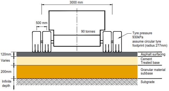
Figure 8. Schematic diagram of the super-heavy load semi-rigid pavement (Vehicle data source from ).
FAARFIELD is widely adopted for its reliability and computational efficiency in conducting structural analyses of airfield pavements. Although it is suitable for general pavement design applications, the program relies on several assumptions and simplifications that may not fully capture the failure mechanisms of CTB layers or the complex behaviour of semi-rigid pavement systems. Therefore, a comparative assessment between the results obtained from FAARFIELD and HIPAVE is warranted to evaluate the applicability and limitations of each approach for modelling SHL semi-rigid pavement structures. Initially, the FAARFIELD procedure was used to determine the required pavement thickness to accommodate the design vehicle with a 90-tonne axle load and the wheel configuration illustrated in Figure 8. The assumed design traffic consists of 400 passes per year over a 25-year design life, with a zero-traffic growth rate. The input subgrade and pavement material parameters used in the analysis are summarised in Table 4.
Table 4. Material properties used in this comparative study.

Layer

Elastic Modulus (MPa)

Poisson’s ratio

Surfacing (asphalt)

1380

0.15

Cement Treated Base (CTB)

5000

0.15

Subbase

500

0.30

Subgrade

30 - 100

0.40

Data source:
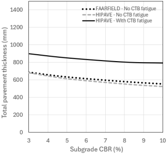
Figure 9. Comparison super-heavy load semi-rigid pavements by FAARFIELD and HIPAVE.
For ease of comparison purposes, the asphalt surfacing thickness was fixed at 120 mm, while the subbase thickness was maintained at 200 mm. The HIPAVE procedure adopts asphalt and subgrade failure criteria similar to those used in the FAARFIELD procedure. It should be noted that HIPAVE is an open-system platform that allows users to define and incorporate customised material failure criteria for individual pavement layers. The effect of pavement thickness variations resulting from different subgrade CBR values was evaluated over a range of 3% to 10% and the results are shown in Figure 9.
The results in Figure 9 demonstrate that the required pavement thickness to withstand the design traffic loading increases as subgrade stiffness decreases. For constant asphalt surfacing and subbase thicknesses, the required CTB thickness is highly dependent on the strength and stiffness of the subgrade. When CTB fatigue criteria are not considered, the pavement thicknesses predicted by HIPAVE are approximately less than 5% lower than those obtained from FAARFIELD. However, when CTB fatigue criteria are incorporated, HIPAVE predicts a substantial increase in the required pavement thickness, ranging from approximately 32% to 51%. These finding highlights that neglecting CTB fatigue failure criteria may result in significant underestimation of the required pavement thickness. Therefore, appropriate CTB failure mechanisms must be incorporated into the design process to ensure reliable and adequate performance of semi-rigid flexible pavement structures.
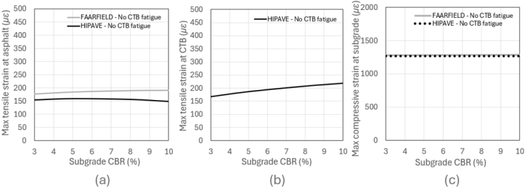
For the purpose of comparing pavement responses between FAARFIELD and HIPAVE, the analyses were conducted without considering CTB failure criteria. Both programs were evaluated using the same pavement configuration, layer thicknesses, and equivalent pavement material properties to ensure a consistent basis for comparison. Figure 10a shows that the pavement response in terms of tensile strain at the bottom of the asphalt layer predicted by HIPAVE is approximately 12-25% lower than that predicted by FAARFIELD. A direct comparison of the tensile strain response at the bottom of the CTB layer cannot be made, as FAARFIELD does not incorporate a CTB fatigue failure criterion, as illustrated in Figure 10b. The predicted vertical compressive strain at the top of the subgrade is relatively comparable between the two approaches, with HIPAVE consistently producing values approximately 1% lower than FAARFIELD, as shown in Figure 10c. The asphalt tensile strain results indicate that, for stronger subgrade conditions, the FAARFIELD design procedure is generally governed by asphalt fatigue performance. In contrast, the HIPAVE procedure appears to be more influenced by CTB fatigue behaviour under strong subgrade conditions, as demonstrated by the increase in CTB tensile strain with increasing subgrade CBR values (Figure 10b). Overall, the pavement response predictions obtained from HIPAVE show good agreement with those from FAARFIELD when CTB failure criteria are excluded. Under these conditions, the HIPAVE modelling approach was successfully verified through benchmarking against the established FAARFIELD design methodology.
Figure 10. (a) Tensile strain at asphalt (b) Tensile strain at CTB (c) Compressive strain at top of subgrade.
8. Case Study
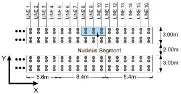
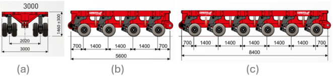
This section presents an efficient approach for designing semi-rigid flexible pavements subjected to SHL movements. A hypothetical case study is considered to demonstrate the proposed design procedure. The total gross weight of the transported load is assumed to be 4480 tonnes and is carried by two SPMTs. Each SPMT consists of an assembly of two 4/4/3.00 Evo3 (70 t) modules and one 6/4/3.00 Evo3 (70 t) module, as illustrated in Figure 11 . The front and rear trailers adopt the same wheel configuration, comprising twin module assemblies. The maximum dimensions of the front trailer are 22.4 m in length and 3.0 m in width, with a module spacing of 2.0 m. The complete SPMT vehicle configuration and loading details are summarised in Table 5 and illustrated in Figure 12.
Figure 11. Cometto SPMT (a) Section view (b) Elevation view 4/4/3.00 Evo3 (70T) (c) Elevation view 6/4/3.00 Evo3 (70T) (Data source: ).
Table 5. Load description of SMPT modules.

Vehicle description

Front trailer

Rear trailer

Total weight (tonnes)

2240

2240

Load/Line (tonnes)

140

140

Load/Axle (tonnes)

70

70

Load/Tyre (tonnes)

17.5

17.5

Aeronautic tubeless tyres

33.5×11.25-15 26Pr

33.5×11.25-15 26Pr

Tyre pressure (kPa)

2180

2180

Data source:
For the parametric study, the semi-rigid flexible pavement configuration, layer thicknesses, and material properties were assumed to remain constant, as summarised in Table 6. The asphalt surfacing layer was modelled as a standard material defined by the FAA and adopted in FAARFIELD. The CTB layer failure criterion was based on the AfPA procedure, calibrated for Ports and Intermodal Terminal pavements. The Barker and Brabston sub-layering approach was implemented in HIPAVE to represent the stress-dependent behaviour of the unbound subbase layer. The subgrade layer was assumed to extend to an infinite depth, with the subgrade failure criterion adopted in HIPAVE calibrated based on aircraft loading conditions.
Figure 12. Schematic illustration of SMPT used in this case study and nucleus segment of SPMT.
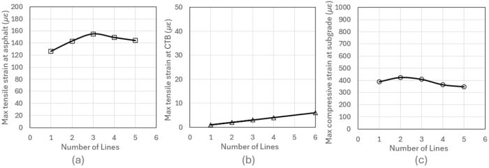
Table 6. Material properties used in HIPAVE.

Material type

Thickness (mm)

Modulus (MPa)

Failure criteria source

Asphalt surfacing

100

1380

FAARFIELD

Cement treated base

200

5000

AfPA

2]

Crushed aggregate subbase

200

500

Barker and Brabston

Subgrade CBR 6%

Infinite

60

HIPAVE

calibrated with aircraft loading

Data source:
8.1. Effect Online Loads
As a first step in identifying a representative load nucleus, an incremental line-load approach was adopted. In this study, a line load is defined as the complete axle load of the twin-trailer configuration considered in the case study, as illustrated in Figure 12. The line loads are progressively added until the inclusion of an additional line load no longer influences the pavement response at the critical point of interest. This means that the stress and strain responses induced at the critical pavement locations have stabilised and are no longer affected by further increases in the applied line load.
Figure 13. Effects of line loads on (a) Tensile strain of asphalt (b) Tensile strain of CTB (c) Compressive strain of subgrade.
A comparison of the pavement responses in the asphalt, CTB, and subgrade layers, as presented in Figure 13, indicates that for the considered pavement configuration and loading conditions, the asphalt layer represents the critical component, with asphalt fatigue damage governing the pavement response. The results further show that three-line loads represent the critical loading configuration for this analysis. These findings demonstrate that the progressive superposition of stresses induced by the applied line loads plays a significant role in governing the overall pavement response.
8.2. Effect of Wheel Number
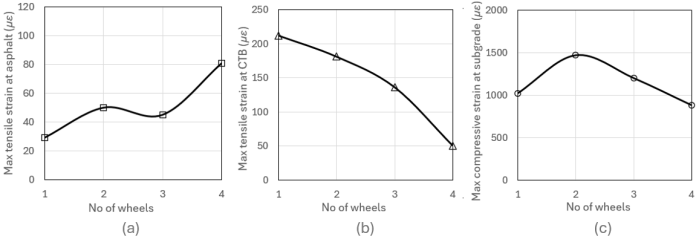
Within each trailer axle configuration, an analysis was conducted to evaluate the influence of increasing the number of wheels on pavement response. For each wheel configuration, an equivalent design traffic loading was applied to maintain consistent loading conditions and determine the critical pavement responses, including the horizontal tensile strain at the bottom of the asphalt and CTB layers, as well as the vertical compressive strain at the top of the subgrade.
Figure 14. Effects of line loads on (a) Tensile strain of asphalt (b) Tensile strain of CTB (c) Compressive strain of subgrade.
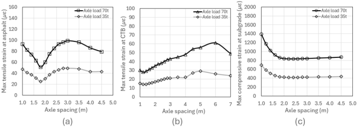
Figure 14a shows that the four-wheel configuration produces the maximum horizontal tensile strain of approximately 80 με in the asphalt layer. This value is less than half of the allowable tensile strain limit of approximately 230 με specified by the FAARFIELD asphalt failure criterion shown in Figure 7. Figure 14b indicates that the single-wheel configuration generates the maximum CTB tensile strain of approximately 212 με, exceeding the allowable tensile strain limit of approximately 155 με based on the AfPA CTB failure criterion as shown in Figure 6. For the subgrade response, the two-wheel configuration results in the maximum compressive strain of approximately 1470 με at the top of the subgrade as shown in Figure 14c, which remains below the allowable limit of 1790 με defined by the HIPAVE subgrade failure criterion, shown in Figure 5. In the case of subgrade, 2 number of wheels generate the maximum compressive strain of 1470 με at the top of subgrade as revealed in Figure 14c compared with the allowable compressive strain of 1790 με as shown in Figure 5 for HIPAVE subgrade failure criteria. Comparison of the pavement responses across the asphalt, CTB, and subgrade layers indicates that the CTB layer represents the governing structural component under the considered loading conditions. The results demonstrate that the CTB layer carries a significant proportion of the structural demand, with CTB fatigue damage controlling the pavement performance.
8.3. Effect on Axle Spacing
For this assessment, axle sensitivity analyses were performed using a four-axle SPMT configuration with axle loads of 70 tonnes and 35 tonnes. A comparison of the pavement responses in the asphalt, CTB, and subgrade layers indicates that, for the considered pavement configuration and loading conditions, the subgrade represents the critical component, with subgrade damage governing the pavement performance as shown in Figure 15a, 15b and 15c. Figure 15c demonstrates that an inter-axle spacing greater than 1.6 m has a negligible influence on the response of adjacent axle wheel loads, whereas the minimum inter-axle spacing of 1.3 m produces a significant interaction effect. This indicates that closely spaced axles result in overlapping stress distributions, leading to increased stress concentrations and greater pavement damage potential. The increased effect of closely spaced axle loads is further amplified by the residual response of pavement materials exhibiting visco-elasto-plastic behaviour, including the asphalt surfacing, CTB, granular subbase, and subgrade layers. The tensile and compressive stresses induced by individual axle loads do not dissipate immediately following each load application; instead, a portion of the stress remains within the pavement structure, resulting in a pre-stressing effect. The accumulation of these residual stresses can accelerate fatigue damage and contribute to premature pavement deterioration .
Figure 15. Effect of axle spacing (a) Tensile strain of asphalt (b) Tensile strain of CTB (c) Compressive strain of subgrade.
For practical considerations, an inter-axle spacing equal to or less than 1.0 m is not feasible due to insufficient horizontal clearance between adjacent tyres. It is worth noting that increasing the inter-axle spacing beyond 1.6 m results in less than a 5% variation in the vertical strain response at the top of the subgrade. In the absence of a specific criterion defining the minimum significant difference between loading conditions, a 5% variation is considered a reasonable engineering tolerance. Interestingly, reducing the axle load by half produces similar pavement response trends, indicating that axle interaction remains a significant factor under different loading magnitudes. This finding is consistent with the study by Varin and Saarenketo , which investigated the influence of inter-axle spacing on heavy vehicle loading behaviour. The results demonstrate that the interaction effects between closely spaced axles cannot be neglected. Given that the SPMT configuration considered in this study has an inter-axle spacing of 1.4 m, all axles should be incorporated in the pavement modelling to accurately capture the combined loading effects.
8.4. Effect on Number of Axles
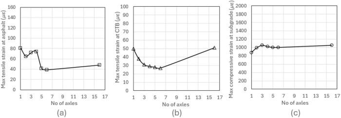
For this study, the standard COMETTO SPMT axle spacing of 1.4 m was progressively increased from one axle to sixteen axles. For each axle configuration, an equivalent design traffic loading was applied to maintain consistent loading conditions. A comparison of the critical responses in the asphalt, CTB, and subgrade layers indicates that subgrade damage governs the pavement performance, as illustrated in Figure 16. The results highlight that the number of axles has a significant influence on pavement strain responses due to the stress superposition effect associated with closely spaced axle loads. Interestingly, the three-axle configuration produced a similar critical response to the sixteen-axle configuration when assessing the worst-case loading condition using mechanistic analysis. This finding suggests that modelling three axles is sufficient to replicate the critical pavement responses generated by the full sixteen-axle configuration.
Figure 16. Effects of number of axles on (a) Tensile strain of asphalt (b) Tensile strain of CTB (c) Compressive strain of subgrade.
8.5. Effect on Trailer Spacing
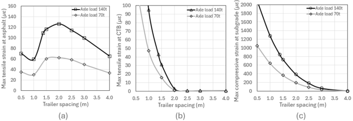
Figure 17. Effects of trailer spacing on (a) Tensile strain of asphalt (b) Tensile strain of CTB (c) Compressive strain of subgrade.

As indicated in Figure 17a, the maximum horizontal tensile strain at the bottom of the asphalt layer occurs at a trailer spacing of 2.0 m, reaching approximately 126 με, which is less than half of the allowable tensile strain limit of approximately 230 με specified by the FAARFIELD asphalt failure criterion as shown in shown in Figure 7. As can be seen in Figure 17b, the influence of adjacent trailer loading on the CTB layer response becomes negligible beyond a spacing of approximately 2.0 m. Similarly, for the subgrade response, the critical vertical compressive strain at the top of the subgrade decreases rapidly with increasing trailer spacing and becomes insignificant beyond approximately 3.0 m, as illustrated in Figure 17c. These findings reveal that the effect of twin-trailer spacing becomes negligible beyond 2 m.
9. Conclusions
Super-heavy load vehicles typically consist of numerous tyres and axles to distribute extremely large weights. This study presents a methodology for conducting mechanistic analysis using a Layered Elastic Theory based program, HIPAVE, to identify a representative nucleus segment and determine the critical pavement responses associated with SHL movements on semi-rigid flexible pavements. By applying SHL nucleus segment, the mechanistic analysis demonstrated that the critical pavement responses generated by the complete SHL configuration can be effectively replicated without the need to model the entire vehicle wheel arrangement. The results indicate that, when adopting the FAA asphalt failure criterion and excluding CTB failure criteria, the HIPAVE design approach produces pavement thicknesses comparable to those obtained from FAARFIELD for a subgrade CBR of 6%. Furthermore, the study highlights that CTB failure criteria should not be neglected, as doing so may result in underestimation of the required pavement thickness and potentially lead to inadequate pavement design. Since FAARFIELD does not incorporate CTB failure criteria, its results should be interpreted with caution when applied to the analysis and design of semi-rigid flexible pavements.
The parametric study demonstrates that increasing the inter-axle spacing beyond 1.6 m results in less than a 5% difference in the vertical strain response at the top of the subgrade. The results further indicate that modelling three axles is sufficient to reproduce the same critical pavement responses as modelling sixteen axles, representing the complete front or rear trailer configuration. The influence of adjacent trailer loading on the CTB and subgrade responses decreases significantly beyond a trailer spacing of 2.0 m, indicating that the interaction effect from adjoining trailers can be neglected. Furthermore, the two-wheel single-axle configuration produced the most conservative pavement responses. However, when all critical pavement responses are considered collectively, the three-wheel single line-load configuration provides a more balanced and conservative representation of the loading effect. Overall, the findings demonstrate that the SHL nucleus segment can be effectively represented by a cluster consisting of three axles with two tyres per axle, which generates the maximum combination of critical pavement responses. It is recommended that further research be undertaken to develop unified design guidelines and long-term field monitoring including the development of a simplified design chart or nomograph to evaluate the effects on semi-rigid flexible pavement performance and to validate mechanistic design approaches subjected to SHL movements.
Abbreviations

AASHTO

American Association of State Highway and Transportation

AC

Asphalt Concrete

AC14M

Asphalt Concrete Size 14 Mm Medium Duty

AfPA

Australian Flexible Pavement Association

APSDS

Airport Pavement Structural System

ARRB

Australian Road Research Board

BAA

British Airports Authority

BPA

British Ports Association

CBR

California Bearing Ratio

CE

Corps of Engineers

CIRCLY

Circular Linear Elastic Analysis

CTB

Cement-Treated Base

DIT

Department of Infrastructure and Transport

DoD

Department of Defence

ESWL

Equivalent Single Wheel Load

FAA

Federal Aviation Administration

FAARFIELD

FAA Rigid and Flexible Interactive Elastic Layer Design

FCAA

French Civil Aviation Authority

FEM

Finite Element Model

FHWA

Federal Highway Administration

HIPAVE

Heavy Industrial Pavement

LET

Layered Elastic Theory

MX

Missile Experimental

NAASRA

National Association of Australian State Road Authorities

PCA

Portland Cement Association

RISAT

Road Infrastructure - Superload Analysis Tool

SHL

Super-heavy Load

SPMT

Self-Propelled Modular Trailers

SuperPACK

Superheavy Load Pavement Analysis PACKage

TRRL

Transport and Road Research Laboratory

TxDOT

Texas Department of Transportation

UFC

Unified Facility Criteria

USACE

U.S. Army Corps of Engineers

Author Contributions
Boon Tiong Chua: Conceptualization, Data curation, Formal Analysis, Investigation, Methodology, Validation, Visualization, Writing – original draft, Writing – review & editing
Kali Prasad Nepal: Writing – review & editing
Data Availability Statement
The data supporting the outcome of this research work has been reported in this manuscript.
Conflicts of Interest
The authors declare no conflicts of interest.
References
[1] Cometto. Catalogue MSPE Self-propelled electronic modules, Borgo San Dalmazzo, Italy; 2017.
[2] Hajj, E. Y., Siddharthan, R. V., Nabizadeh, H., Elfass, S., Nimeri, M., Kazemi, S. F., Batioja-Alvrez, D. D., Piratheepan, M. Analysis procedures for evaluating superheavy load movement on flexible pavements, Volume I: Final Report, Publication No. FHWA-HRT-18-049, Federal Highway Adminstration, Washington, DC; 2018.
[3] Koh, Y., Ceylan, H., Kim, S., Cho, I. H. Development of approaches to quantify superloads and their impacts on Iowa road infrastructure system, Report No. IHRB Project TR-781, Instute for Transportation, Iowa State University, Ames, IA, USA; 2024.
[4] Barber, V. C., Ladd, D. M. Pavement design criteria for heavy-load vehicles, Transportation Research Record 949, U.S. Army Engineer Waterways Experiment Station, Corps of Engineer, Vicksburg, Miss. USA; 1983.
[5] Jooste, F. J., Fernando, E. G. Development of a procedure for the structural evaluation of superheavy load routes, Report No. FHWA/TX-97/1335-3F, FHWA Contract No. 0-1335, Texas Transportation Institute, College Station, Texas, USA; 1995.
[6] Chen, D. H., Fernando, E., Murphy, M. Application of falling weight deflectometer data for analysis of superheavy loads, Transportation Record 8; 1996.
[7] Chen, X., Lambert, J. R., Tsai, C., Zhang, Z. Evaluation of superheavy load movement on flexible pavements, International Journal of Pavement Engineering, Taylor & Francis; 2012.
[8] Asphalt Institute. Research and development of asphalt institute’s design manual (MS-1) Ninth Edition, Research Report No. 82-2, USA; 1982.
[9] Nimeri, M. A. Evaluating superheavy load moverment on flexible pavements: Identifying load nucleus and elements of bearing capacity investigation, M. Sc. Thesis, University of Nevada, Reno, Nevada, USA; 2016.
[10] Skaff, R. S. Superheavy load pavement analysis PACKage (SuperPACK): Verfication and modification, M.Sc. Thesis, University of Nevada, Reno, USA; 2021.
[11] Skaff, R. S. Case studies for risk assessment of superheavy load movements on flexible pavements using SuperPACK, Ph. D. Dissertation, University of Nevada, Reno, USA; 2024.
[12] Khanal, S., Olidis, C., Hein, D. K. Modelling pavement responses to superheavy load movement, Conference of the Transportation Association of Canada, Toronto, ON, Canada; 2016.
[13] Vandenbossche, J. M., Donnelly, C. A., Buettner, N., Sen, S., Brody, Z. Effect of superloads on pavement life (WO19), Report No. FHWA-PA-2022-001-PITT WO 019, Unversity of Pittsburgh, Pittsburgh, PA, USA; 2021.
[14] Perez-Gonzalez, E. L. Development of an analysis tool to quantify the effect of superheavy load vehicles on pavements, Ph. D. Dissertation, University of Laval, Quebec, Canada; 2021.
[15] Austroads. Guide to pavement technology Part 2: Pavement Structural Design, Austroads Publication No. AGPT02-25, Sydney, NSW, Australia; 2025.
[16] Yoder, E. J., Witczak, M. W. Principles of pavement design, 2nd Edition, John Wiley and Sons; 1975.
[17] Hein, D. K., Jung, F. W. Assessment techniques to determine pavement damage due to heavy loading, Conference of the Transportation Association of Canada Regina, Sasatchewan; 1998.
[18] Koh, Y., Ceylan, H., Kim, S., Cho, I. H. Critical response of flexible pavements under superheavy loads and data-driven surrogate model, International Journal of Pavement Research and Technology; 2023, 16, 513-543.
[19] Nimeri, M., Nabizadeh, H., Hajj, E., Siddharthan, R. V., Elfass, S. Analysis procedures for evaluating superheavy load movement on flexible pavements, Volume III: Appendix B, Superheavy Load Configurations and Nucleus of Analysis Vehicle. No. FHWA-HRT-18-051. Federal Highway Administration, Office of Infrastructure Research and Development, United States; 2018.
[20] Barker, W., Brabston, W. Development of a structural design procedure for flexible airport pavements, Report No. S-75-17, US Army Corps of Engineers, Waterways Experiment Station, Vicksburg, Miss., USA; 1975. ISSN: 0360-859X.
[21] Federal Aviation Administration (FAA). FAARFIELD 2.1.1 User manual, Washington, DC, USA; 2023.
[22] Federal Aviation Administration (FAA). AC 150/5320-6G, Airport pavement design and evaluation, USA; 2021.
[23] Fulton Hogan. PortPhalt: A highly modified asphalt designed for use at ports and intermodal terminals, Australia; 2024.
[24] Australian Flexible Pavement Association (AfPA). Performance-based airport asphalt model specification, Version 2.1, Australia; 2023, pp. 49.
[25] National Asphalt Pavement Association (NAPA). Design & construction of heavy-duty pavements, Second Edition, Quality Improvement Series 123, Lanham, Maryland, USA; 2019, pp. 70.
[26] Gaspard, K. J. Evaluation of cement treated base courses, Technical Assistance Report No. 00-1TA, Louisiana Transportation Research Center, Baton Rouge, LA, USA; 2000.
[27] Ashtiani, R. S., Rashidi, M., Rodriguez, E., Ordaz, M., Lopez, H. C., Garay, G., Rocha, S., Garibay, J. Established of best practices for construction and design of cement-treated materials, Texas Department of Transportation, Report No. FHWA/TX-21/0-6949-1, Austin, Texas; 2020.
[28] Koh, Y., Lu, Y., Wiggins, R., Kim, Y., Qamhia, I. I. A., Tutumluer, E., Tingle, J., Parsons, T., Harrell, M. J. Performance prediction models for flexible and rigid pavements - state-of the practice review for implementation in North America, International Journal of Pavement Engineering, USA; 2025, 26(1), pp. 29.
[29] HIPAVE. User manual Revision 5.0. Mincad Systems, Australia; 2009.
[30] Shen, S., Carpenter, S. H. Developement of an asphalt fatigue model based on energy principles, Asphalt Paving Technology 2007 AAPT, San Antonio, Texas, USA; 2007, 76, 525-573.
[31] Finn, F., Saraf, C., Kulkarni, R., Nair, K., Smith, W., Abdullah, A. The use of distress prediction subsystems for the design of pavement structures, Proceedings, 4th International Conference on the Structural Design of Asphalt Pavements, University of Michigan. Ann Arbor, MI, United States; 1977.
[32] United States Army Corps of Engineers (USACE). User guide PCASE7 version 7.0.7, Transportation Computer Assisted Structural Engineering, USA; 2024.
[33] Department of Defence (DoD). Unified Facilities Criteria (UFC). UFC 3-260-02 Pavement design for airfields, USA; 2001.
[34] Chen, D. H., Bilyeu, J, Chang, J. R. A review of the superheavy load permitting programme in Texas, The International Journal of Pavement Engineering; 2005, 6(1), 47-55.
[35] Australian Flexible Pavement Association (AfPA). A guide to the structural design of flexible pavements for ports and container terminals. Port Melbourne, Victoria, Australia; 2021, 129pp.
[36] Department of Infrastructure and Transport (DIT). Master specification part RD-PV-D1 Pavement investigation and design, South Australia, Australia; 2024.
[37] Shell, Shell pavement design manual - Asphalt pavements and overlays for road traffic, Shell International Petroleum Company Limited, London, UK; 1978.
[38] Hossain, M. S., Nair, H., Ozyildirim, H. C. Determination of mechanical properties for cement-treated aggregate base, Charlottesville, VA, USA; 2017.
[39] British Ports Association (BPA). The structural design of heavy-duty pavements for ports and other industries, 3rd Edition, Interpave, Leicester, UK; 1996.
[40] Chua, B. T., Nepal, K. P. Evaluation of design techniques for extra heavy-duty flexible pavements and other critical considerations, American Journal of Civil Engineering; 2025, 13(6), pp. 329-349.
[41] HIPAVE 5 Pavement design workshop notes. Mincad Systems, Australia; 2023.
[42] United States Army Corps of Engineers (USACE). PCASE design workshop material, USA; 2026.
[43] Thompson, M. Thickness design for cement-treated base pavements, Illinois Center for Transportation Series No. 24-015, Research Report No. FHWA-ICT-24-013, Illinois, USA; 2024.
[44] Larsen, T. T., Nussbaum, P. J. Fatigue of soil cement, Bulletin D119, Portland Cement Association (PCA), USA; 1967.
[45] Pretorius, P. C. Design considerations for pavements containing soil-cement bases, Ph. D. Thesis, University of California, Berkeley, California, USA; 1970.
[46] Shackel, B. The analysis and design of concrete block paving subject to road and heavy industrial loading, Proc. Second Int. Conference on Concrete Block Paving, Delft; 1984, pp 136-146.
[47] Shackel, B. Design and construction of interlocking concrete block pavements; 1990.
[48] Vroombout, F., Monteith, R., Sharp, K. G. The use of interlocking concrete blocks on an aircraft pavement in Australia, PAVE 92 Conference, Australia; 1992.
[49] National Association of Australian State Road Authorities (NAASRA). Pavement design - A guide to the structural design of road pavements, SR No. 31, Australia; 1987.
[50] Australian Road Research Board (ARRB). Framework for the revision of Austroads design procedure for pavements containing cemented materials, Australia; 2014.
[51] Gonzalez, A., Jameson, G., de Carteret, R., Yeo, R. Laboratory fatigue life of cemented material in Australia. Road Materials and Pavement Design, Australia; 2013, 14(3), 518-536.
[52] Carpenter, S. H., Ghuzlan, K. A., Shen, S. A fatigue endurance limit for highway and airport pavements, Transportation Research Records, Transportation Research Board, USA; 2003, (1832), 131-138.
[53] Woodman, G. Failure criteria for flexible pavement, PSA report for BAA Technical Services Division, Surrey, UK; 1992.
[54] Rodway, B. Design of flexible pavements for large multi-wheeled aircraft, Second International Conference on Road and Airfield Pavement Technology, Singapore; 1995.
[55] Wardle, L. J., Roadway, B. Layered elastic design of heavy-duty and industrial pavements, Proc. AAPA Pavement Industry Conf., Surfers Paradise, Australia; 1998, pp. 9.
[56] Transport and Road Research Laboratory (TRRL). A guide to the structural design of pavements for new roads, Road Note 29, Third Edition, HMSO, UK; 1970.
[57] Brown, S., Brunton, J. Improvements to pavement subgrade strain criterion. Journal of Transportation Engineering, ASCE, USA; 1984, 110(6), 551-567.
[58] Rahman, M. D., Beecham, S., McIntyre, E., Iqbal, A. Mechanistic design of concrete block pavements, Proceedings 2018 Australian Geomechanics Society Victoria Symposium, Geotechnics and Transport Infrastructure, Melbourne, Victoria, Australia; 2018, 13-17.
[59] Turnbull, W. J., Foster, C. R., Ahlvin, R. G. Design of flexible airfield pavements for multiple wheel landing gear assemblies; Analysis of existing data, Technical Memorandum No. 3-349, Report 2, U.S. Army Engineer Waterways Experiment Station, Corps of Engineers, Vicksburg, Miss, USA; 1955.
[60] Wardle, L. J., Rodway, B., Richards, I. Calibration of advanced flexible aircraft pavement design method to S77-1 method, Advancing aircraft pavements, American Society of Civil Engineers, 2001 Aircraft Pavement Specialty Conference, Chicago, Illinois, USA; 2001, 192-201.
[61] APSDS. User manual. Revision 5.0.700. MinCAD Systems, Australia; 2019, pp. 100.
[62] Pereira, A. T. Procedures for development of CBR design curves. Instruction report S-77-1, Final report, U.S. Army Engineer Waterways Experiment Station, Corps of Engineers, Vicksburg, Miss, USA; 1977.
[63] Gonzalez, C. R., Barker, W. R., Blanchini, A. Reformulation of the CBR procedure, ERDC/GSL TR-12-16; Report I: Basic Report, US Army Corps of Engineers, USA; 2012.
[64] Gonzalez, C. R., Baker, W. R. Implementation of a new flexible pavement design procedure for U.S. military airports, Fourth LACCEI International Latin American and Caribbean Conference for Engineering and Technology and Technology, Mayaguez, Puerto Rico; 2006, pp. 10.
[65] Miller, E. J. Revised beta criteria for the CBR airfield pavement design method, M. Sc. Thesis, The Pennsylvania State University, USA; 2012.
[66] Moffat and Nichol. Container terminal and intermodal rail yard operational area consideration for pavement design. USA; 2012.
[67] Fernando, E. G., Liu, W., Leidy, J. Analysis procedure for load-zoning pavements, Transportation Research Record, Journal of the Transportation Research Board, 1980, USA; 2003, 117-125.
[68] Fernando, E. G., Oh, J. H. Guidelines for evaluating routine overweigth truck routes, College Station, TX: Texas Transportation Institure (Final Report); 2004.
[69] French Civil Aviation Authority (FCAA). Rational design method for flexible airfield pavements, Technical guide, STAC, France; 2016.
[70] Federal Aviation Administration (FAA). Development of new subgrade failure model for flexible pavements in FAARFIELD, DOT/FAA/TC-17/28 Final report prepared by Kawa, I., Washington, DC, USA; 2017.
[71] CIRCLY 7.0. User manual. Mincad System Pty Ltd, Australia; 2022.
[72] Australian Flexible Pavement Association (AfPA). Background to the AfPA guide to the structural design of flexible pavements for ports and container terminals, Port Melbourne, Victoria, Australia; 2022.
[73] Otte, E. A structural design procedure for cement-treated layers in pavements, D. Sc. (Eng) dissertation, University of Pretoria, Pretoria, South Africa; 1987.
[74] Kristjansdottir, R. Design of heavy-duty pavements. Highway Engineering Degree Thesis. KTH Royal Institute of Technology, Stockholm, Sweden; 2017.
[75] Varin, P., Saarenketo, T., The effect of new tyre type, tyre pressure and axle configurations of heavy trucks on asphalt pavement lifetime, 6th Eurasphalt & Eurobitume Congress, Prague, Czech Republic; 2016, pp. 10,
Cite This Article
  • APA Style

    Chua, B. T., Nepal, K. P. (2026). Design of Semi-rigid Pavements for Super-heavy Load Movements: Review and Evaluation of Critical Design Parameters. American Journal of Civil Engineering, 14(4), 253-272. https://doi.org/10.11648/j.ajce.20261404.14

    Copy | Download

    ACS Style

    Chua, B. T.; Nepal, K. P. Design of Semi-rigid Pavements for Super-heavy Load Movements: Review and Evaluation of Critical Design Parameters. Am. J. Civ. Eng. 2026, 14(4), 253-272. doi: 10.11648/j.ajce.20261404.14

    Copy | Download

    AMA Style

    Chua BT, Nepal KP. Design of Semi-rigid Pavements for Super-heavy Load Movements: Review and Evaluation of Critical Design Parameters. Am J Civ Eng. 2026;14(4):253-272. doi: 10.11648/j.ajce.20261404.14

    Copy | Download

  • @article{10.11648/j.ajce.20261404.14,
      author = {Boon Tiong Chua and Kali Prasad Nepal},
      title = {Design of Semi-rigid Pavements for Super-heavy Load Movements: Review and Evaluation of Critical Design Parameters},
      journal = {American Journal of Civil Engineering},
      volume = {14},
      number = {4},
      pages = {253-272},
      doi = {10.11648/j.ajce.20261404.14},
      url = {https://doi.org/10.11648/j.ajce.20261404.14},
      eprint = {https://article.sciencepublishinggroup.com/pdf/10.11648.j.ajce.20261404.14},
      abstract = {This study examines the effects of super-heavy (SHL) vehicles on semi-rigid flexible pavements using various pavement design methodologies. At present, no standardised framework exists for the design of semi-rigid flexible pavements subjected to SHL movements. Current practice commonly relies on performance models originally developed for conventional heavy vehicles; however, the applicability of these models to SHL conditions remains questionable and may result in significant underestimation of pavement damage. In this study, critical pavement responses are simulated mechanistically using the commercially available Mechanistic-Empirical pavement design software HIPAVE, following a benchmarking process against the FAARFIELD program. A hybrid set of pavement materials failure criteria is incorporated into the HIPAVE to simulate pavement responses under SHL operations. The simulation results obtained from HIPAVE show good agreement with those generated by FAARFIELD, demonstrating a reliability of the adopted modelling approach. Furthermore, a novel approach based on the concept of a representative SHL nucleus is proposed to characterise super-heavy loading configurations, enabling efficient assessment of pavement impacts while significantly reducing computational time. The findings from the literature review and numerical analyses indicate that further research is required to establish unified design guidelines and long-term field monitoring including the development of a simplified design chart or nomograph for semi-rigid flexible pavements subjected to SHL movements.},
     year = {2026}
    }
    

    Copy | Download

  • TY  - JOUR
    T1  - Design of Semi-rigid Pavements for Super-heavy Load Movements: Review and Evaluation of Critical Design Parameters
    AU  - Boon Tiong Chua
    AU  - Kali Prasad Nepal
    Y1  - 2026/07/30
    PY  - 2026
    N1  - https://doi.org/10.11648/j.ajce.20261404.14
    DO  - 10.11648/j.ajce.20261404.14
    T2  - American Journal of Civil Engineering
    JF  - American Journal of Civil Engineering
    JO  - American Journal of Civil Engineering
    SP  - 253
    EP  - 272
    PB  - Science Publishing Group
    SN  - 2330-8737
    UR  - https://doi.org/10.11648/j.ajce.20261404.14
    AB  - This study examines the effects of super-heavy (SHL) vehicles on semi-rigid flexible pavements using various pavement design methodologies. At present, no standardised framework exists for the design of semi-rigid flexible pavements subjected to SHL movements. Current practice commonly relies on performance models originally developed for conventional heavy vehicles; however, the applicability of these models to SHL conditions remains questionable and may result in significant underestimation of pavement damage. In this study, critical pavement responses are simulated mechanistically using the commercially available Mechanistic-Empirical pavement design software HIPAVE, following a benchmarking process against the FAARFIELD program. A hybrid set of pavement materials failure criteria is incorporated into the HIPAVE to simulate pavement responses under SHL operations. The simulation results obtained from HIPAVE show good agreement with those generated by FAARFIELD, demonstrating a reliability of the adopted modelling approach. Furthermore, a novel approach based on the concept of a representative SHL nucleus is proposed to characterise super-heavy loading configurations, enabling efficient assessment of pavement impacts while significantly reducing computational time. The findings from the literature review and numerical analyses indicate that further research is required to establish unified design guidelines and long-term field monitoring including the development of a simplified design chart or nomograph for semi-rigid flexible pavements subjected to SHL movements.
    VL  - 14
    IS  - 4
    ER  - 

    Copy | Download

Author Information