Review Article | | Peer-Reviewed

A Review of the Performance Criteria and Key Design Input Parameters for Jointed Plain Concrete Pavements

Received: 24 May 2025     Accepted: 11 June 2025     Published: 30 June 2025
Views:       Downloads:
Abstract

The design of Jointed Plain Concrete Pavement (JPCP) is typically carried out using the total fatigue and/or erosion damage models, based on the requirements outlined in the design brief or the specific practical conditions. The fatigue failure and erosion damage models criteria are widely recognised and used globally to evaluate the performance of JPCP. The performance failure criterion is inherently tied to the design methods, making it unsuitable for direct comparison with other methods in isolation. But the most widely used the mechanistic-empirical design procedure for JPCP is heavily reliant on the calibration of these damage models, which illustrate the relationship between stress ratio (the allowable flexural stress divided by the modulus of rupture) and the allowable number of load repetitions for a specific axle load. The induced flexural stress in the pavement is influenced by numerous factors, including foundation support conditions, axle loads, load locations (interior, edge and corner), design traffic loading, tyre pressure, concrete properties, slab size (with and without concrete shoulders), the ratio of joint spacing to radius of relative stiffness, and other key design parameters. This paper presents an extensive literature review of these key design factors that influence the design of JPCP, with the aim of enhancing the understanding of pavement behaviour and optimising pavement performance for cost-effective designs. The literature review also reveals that erosion distress prediction model developed by Portland Cement Association is based primarily on granular subbase materials which is dated and the benefit of using as non-erodible subbase materials is not incorporated in the performance assessment. Furthermore, the integration of a more robust faulting damage model would require significant advancements, indicating a clear need for further research in this area. The analysis further reveals that the thickness of concrete pavement is relatively insensitive to modest changes in the modulus of subgrade reaction (K). Additionally, it shows that the allowable joint spacing increases with greater slab thickness but decreases as the K-value rises. The average reduction in slab thickness is found to be approximately 12% when concrete shoulders are used in the design. The findings underscore the importance of integrating various design aspects of JPCP, rather than treating them as a series of isolated activities or materials, in order achieve optimal pavement performance.

Published in American Journal of Civil Engineering (Volume 13, Issue 3)
DOI 10.11648/j.ajce.20251303.15
Page(s) 165-184
Creative Commons

This is an Open Access article, distributed under the terms of the Creative Commons Attribution 4.0 International License (http://creativecommons.org/licenses/by/4.0/), which permits unrestricted use, distribution and reproduction in any medium or format, provided the original work is properly cited.

Copyright

Copyright © The Author(s), 2025. Published by Science Publishing Group

Keywords

Jointed Plain Concrete Pavement, Stress Ratio, Radius of Relative Stiffness, Modulus of Subgrade Reaction

1. Introduction
Jointed Plain Concrete Pavements (JPCPs) are the most used type of cast-in-place concrete pavements worldwide . They are generally regarded as the most cost-effective option in terms of both initial construction and long-term maintenance. Due to their durability and economic advantages, JPCPs are widely used across a range of applications, including road pavements, bus lanes, parking areas, industrial pavements, airport pavements, and intermodal container terminals (ICT) ports. Figure 1 illustrates the schematic diagram of a typical JPCP system, which serves as a basis for calculating traffic-induced stresses distributed across the concrete slab.
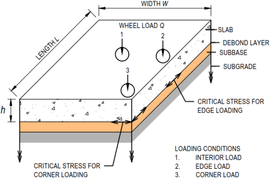
Figure 1. Schematic diagram of JPCP system.
Concrete pavements are susceptible to uncontrolled cracking when exposed to thermal and mechanical stresses resulting from drying shrinkage, thermal expansion, temperature gradients, traffic loading and potential soil swelling . These uncontrolled cracks not only compromise the visual appearance of the pavement but also progressively reduce load transfer efficiency as the crack width increases over time, ultimately leading to structural failure. In JPCPs, the formation of cracks can be effectively mitigated by segmenting the pavement into discrete slabs using transverse and longitudinal joints. JPCPs are typically unreinforced; however, reinforcement may be utilised selectively in non-standard configurations, such as irregularly shaped panels, end transitions, drainage inlets and ramp gores. Load transfer across adjacent slabs is primarily achieved through aggregate interlock and dowel bars, the latter of which are commonly installed across transverse joints to enhance load transfer efficiency, particularly in heavily trafficked areas. Additionally, tie bars are placed across longitudinal joints to maintain slab alignment and ensure structural continuity between adjacent slabs .
The long-term performance of JPCPs depend on effective pavement design, sound construction practices and appropriate material selection. Key design factors, including joint spacing, slab thickness, joint transfer efficiency with and without dowels, foundation support, as well as loading and environmental conditions, play an essential role in ensuring the structural integrity and durability of the pavements . Consequently, the primary aim of this paper is to provide a comprehensive review of JPCP design methods, performance failure criteria, and other key parameters such as stress ratios, the influence of shoulders, the radius of relative stiffness, the ratio of joint spacing to radius of relative stiffness, which affect the critical stresses in JPCP. By addressing these factors, the paper seeks to facilitate the development of an integrated design approach that optimises pavement performance. It is important to note that this paper does not covers construction practices and material selection, as these topics are extensively addressed in various manuals, technical advisories, and design information bulletins by relevant agencies.
2. Concrete Pavement Design Methods
The engineering principles underlying JPCP used in road infrastructure have been established over 120 years , 5]. Comprehensive design methodologies for concrete pavements in road, airfield, and industrial applications are well established across various regions, including Australia, the United States, Europe and others. Existing approaches for determining stresses and strains in concrete pavements can be broadly classified into six categories: (1) analytical approaches using closed-form mathematical expressions without empirical approximation; (2) influence diagrams; (3) elastic layer theories; (4) numerical methods (5) empirical and design catalogues methods; and (6) mechanistic-empirical procedures. Each of these approaches offers distinct advantages and limitations, and their application is typically governed by the complexity of the design problem, the availability of input data, and the desired level of accuracy.
2.1. Analytical Approaches
The earlier analytical models for the theoretical analysis of concrete pavements were developed by Westergaard and continue to underpin many modern design methods. These models conceptualise the concrete pavement as a thin elastic plate resting on a bed of independent springs. The pavement itself is characterised by elastic material properties, including Poisson’s ratio and modulus of elasticity, while the supporting subbase and subgrade layers are idealised by a spring constant, referred to as the modulus of subgrade reaction (K). This idealisation of the supporting layers as a bed of linear springs assumes homogeneity and linearity, which may not accurately represent the conditions where one or more supporting layers have been stabilised or treated to enhance stiffness and strength. Westergaard’s method involves calculating the stresses in the concrete slab under the wheel load, assuming an infinite or semi-infinite slab subjected to an equivalent load from a single wheel. For multiple wheel load configurations, the analysis distinguishes three primary loading scenarios: interior loading (centre of the slab), edge loading, and corner loading. These scenarios are represented by Equations (1) to (3).
σj=0.275(1+μ)Qh24log10lb+1.069 (1)
σe=0.529(1+0.54μ)Qh24log10lb+0.359(2)
σc=3Qh21-a2l0.6(3)
The Westergaard method assumes that there is no structural connection between adjacent concrete slabs, effectively treating each slab as an isolated unit. While this assumption simplifies the analysis, it is considered conservative, as substantial load transfer- typically up to 70%- can occur across joints in well-constructed JPCP. Moreover, the Westergaard model does not account for stresses induced by environmental factors, such as thermal curling and pumping (erosion). Curling stresses, which result from temperature gradients across the slab thickness, are often neglected in the analysis, as they typically occur once per day and are therefore considered less critical than the repetitive traffic-induced stresses experienced throughout the pavement’s life. It is also important to note that the applicability of the Westergaard equations is limited to slabs with dimensions greater than 3.5 times the radius of relative stiffness (𝑙).
In contrast to the other two loading conditions, the original Westergaard equation for corner loading remains the least understood and most debated. Its theoretical basis for estimating maximum corner stress has been regarded as inadequate . The equation is semi-empirical, lacks a closed-form solution, and employs approximations to overcome specific mathematical challenges. Moreover, it suffers from a limited body of experimental validation. This shortcoming has led to numerous revisions and modifications aimed at validating theoretical predictions with observed slab performance in the field. These revisions have been explored by several researchers and are summarised in Equations (4) to (10).
σc=3Qh21-cl0.72(4)
σc=3Qh21-a2l1.2(5)
σc=3Qh2(6)
σc=3Qh21-al0.6(7)
σc=3.2Qh21-a2l(8)
σc=4.2Qh21-al0.50.925+0.22al(9)
σc=3Qh21.2al2-2al+1.1(10)
All these corner stress formulas can be expressed in the form of a generalised Equation (11).
σc=CQh2(11)
where C is a dimensionless coefficient that is independent of ratio Q/h2 and is a function of a/l ratio. For comparison purposes, constant input parameters are assumed, including slab thickness, concrete properties (E and μ), subbase and subgrade conditions, and a consistent tyre footprint to compute C using these formulas. The results are presented in Figure 2, which illustrates the variation of C as a function of the a/l ratio. The figure demonstrates that C consistently decreases with increasing a/l ratio in all cases examined. The equations proposed by Westergaard and Pickett serve as lower and upper bound solutions, respectively. Notably, Westergaard curve shows a more rapid decline in C values as the a/l ratio increases.
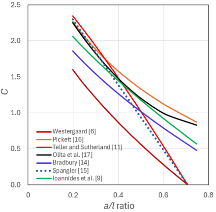
Figure 2. C versus a/l ratio.
2.2. Influence Diagrams
Pickett and Ray developed influence diagrams that simplified the complex calculations required by Westergaard analytical solutions. They later introduced computerised solutions for the interior load condition, a development that was extended by Kreger to address the edge load cases. Eberhardt further advanced the approach by using refined numerical integration technique to accommodate the demands by larger military aircraft. Witczak et al. proposed a regression equation to calculate the Westergaard’s free edge stress.
2.3. Elastic Layer Theories
The limitations of the Westergaard model in accurately charactering the materials beneath concrete slabs have led to increased interest in employing layered elastic analysis to calculate stresses. In this approach, the pavement structure is idealised as a series of infinite, uniform horizontal layers with homogeneous and isotropic properties, characterised by a modulus of elasticity and a Poisson’s ratio, subjected to circular uniform loads. For multi-wheel loading scenarios, the principle of superposition can be applied. However, the integrals inherent in layered elastic models are not analytically solvable and must be evaluated numerically . A key advantage of layered elastic analysis is its ability to determine the complete state of stresses at any point within the pavement structure. Nonetheless, a significant limitation of elastic layered theory is that it is restricted to interior loading cases and thus cannot be used to evaluate edge or corner stresses nor can it account for joint conditions.
2.4. Numerical Methods
The limitations of the Westergaard and layered elastic models have spurred interests in numerical methods, such as finite element and finite difference techniques. Numerical analysis offers an alternative to analytical, empirical and experimental approaches, offering solutions to many of the shortcomings inherent in these methods. It is particularly adept at handling complex loading conditions, intricate geometries, variable material properties, anisotropy, layered soils, and complex stress-strain relationships . However, as the finite element modelling programs become more advanced, the demands for input data preparation, output analysis, computational resources, and accurate material characterization have also increased significantly. Moreover, analysing the results of finite element models can be challenging, making it difficult to justify the use of numerical techniques for routine small to medium-size projects. Consequently, Westergaard models remain the most widely used methods for calculating stresses in standard design procedures.
2.5. Empirical Methods and Design Catalogues
The existing empirical design methods are primarily based on test data collected over sixty years ago. The most widely used empirical method is the American Association of State Highway and Transportation Officials . Several state highway agencies have utilised the AASHTO Interim Guide procedure , the Portland Cement Association procedure , Cement Concrete Association Australia (CCAA) method , UK Transport Research Laboratory Research Report (TRL RR87) empirical procedure and Technical Report No. 66 (TR 66) method , by Concrete Society in the United Kingdom. The empirical design procedure relies entirely on past observations of field performance and no provision for extrapolating beyond the range of these observations. In addition to the United States, design catalogue approaches have also been adopted in Hong Kong and several European countries, including United Kingdom, Belgium, Germany and France . However, these design catalogue approaches generally lack detailed discussions of the underlying design criteria, making it difficult to assess their relevance or applicability to specific design conditions, such as higher axle loads or extreme winter conditions.
2.6. Mechanistic-empirical Procedure
The fully mechanistic procedure permits unrestricted extrapolation beyond past observations, provided that the fundamental understanding of the material characterisation of in-service pavements is established. Due to complexity involved, the fully mechanistic procedure remains an idealised concept that is not practically achievable. As a result, mechanistic-empirical procedure falls in between fully empirical and fully mechanistic methods. The current trend is to update empirical procedure to mechanistic-empirical frameworks. The most widely used mechanistic-empirical methods are Mechanistic-Empirical Design Guide in the United States, Austroads in Australasia, and Indian Road Congress (IRC) method in South Asia.
The comprehensive review of the concrete pavement design reveals a significant shift from early empirical methods to mechanistic-empirical methods and trending towards mechanistic approaches. This evolution is largely driven by the advent of high-speed computing and advanced testing techniques, which enable more accurate material characterization.
3. Performance Criteria
3.1. Pavement Damage
Traditionally, fatigue cracking has been regarded as the primary or sole criterion in the design of concrete pavements. However, recent studies have highlighted erosion damage as an additional, significant factor contributing to pavement failure. Concrete pavements are subjected to the effects of fatigue, caused by repeated traffic loading and temperature fluctuations. The cumulative effect of each incremental load-induced damage over time leads to fatigue cracking and faulting. Miner’s Rule, which posits that for a given stress level, the damage fraction can be determined as the ratio of the number of cycles at that stress level to the total number of cycles to failure under the same stress level, is commonly used to account for cumulative damage . Based on the established relationship between accumulative damage and the number of allowable load repetitions, the Cumulative Damage Factor (CDF) is calculated. The CDF is defined as the ratio of cumulative damage to the allowable number of repetitions.
3.2. Performance Models
PCA pavement performance models are widely used and address both fatigue and erosion performance criteria. The erosion criterion has been further refined to incorporate variables from existing faulting models, including two faulting prediction models- one for doweled and one for undowelled joints- using nonlinear regression analysis. This refinement also considers factors such as concrete shoulders, undowelled joints, stabilised subbases, higher traffic volumes, and extended service life .
In the US, the NCHRP developed a fatigue criterion with a 90% reliability level, which was incorporated into the Mechanistic-Empirical Pavement Design Guide (MEPDG). In the UK, the failure criteria established in Transport Research Laboratory Research Report 87 (TRL RR87) are widely used . An empirical regression equation for unreinforced concrete pavement failure was developed based on a set of defined failure criteria. These criteria differ between unreinforced and reinforced concrete slabs, meaning that the applicability of these regression equations must be considered within these context-specific limitations. Technical Report No. 66, published by Concrete Society , which addresses external in-situ concrete paving, employs the same failure criteria from TRL RR87 for the design of both unreinforced and conventionally reinforced pavements.
Austroads performance model considers both structural fatigue in the concrete slab and subbase erosion as distress modes. These distress modes are linked to induced flexural fatigue cracking of the base slab and erosion in subgrade/subbase area under joints or cracks caused by the effects of deflections from repeated loads. These performance models are based on those of PCA in the US, with modifications made to better align Australian conditions . However, it appears that Austroads performance models may be overly conservative, particularly when using erosion distress as the design criterion, even though lean mix concrete is used as the subbase layer. A review of Austroads performance models could potentially lead to a reduction in the slab thickness, offering cost savings and sustainability benefits . Indian Roads Congress and Department of Roads, Nepal have both adopted the fatigue criteria developed by PCA , which are considered conservative and are applicable for analysing both bottom-up and top-down cracking. The concrete pavement performance models used by different agencies and outlined in literature are summarised in Table 1.
Table 1. Summary of concrete pavement performance models.

Agency / Researcher

Relationship

Comments

Murdock & Kesler

Fatigue distress mode#:

log10Nf=0.9453-SR0.019 r = 25%

log10Nf=0.9490-SR0.006 r = 75%

The results of the plain beam tests are summarised using a regression curve, with the loading range expressed as the ratio of flexural stress at minimum load to the stress at maximum load r. The ratio r increases with flexural strength. However, it is important to note that traffic loading conditions in the field may differ significantly from those observed in laboratory tests, which can affect the applicability of the results.

Ballinger

(FHWA)

Fatigue distress mode#:

log10Nf=0.9194-SR0.011 for 100Nf107

Regression curve derived from beam bending tests is subject to the same limitations as laboratory-based results may not fully capture the complexities and variations in traffic loads encountered in the field, potentially affecting the accuracy and applicability of the regression model

Darter

(FHWA)

Fatigue distress mode:

log10Nf=17.61-17.61SR

The mean regression curve based on fatigue data obtained from these studies using plain PCC beams. Nordby

, Raithby and Galloway and Ballinger was developed for a 50% failure probability.

PCA

Fatigue distress mode:

Nf=unilmited for SR<0.45

Nf=4.2577SR-0.43253.268for 0.45SR0.55

log10Nf=11.737-12.077SR

Erosion distress mode:

log10Ne=14.524-6.777(C1(p-9)0.103

C1 = 1.0 and 0.90 for normal and high strength subbase respectively

The stress ratio for unlimited repetitions, initially set at 0.50, has been revised down to 0.45 to better align with the increasing volume of truck traffic. The widely used fatigue equation, which is based on a failure probability lower than the 50% threshold proposed by other studies, is therefore considered conservative in its predictions. Furthermore, the erosion prediction criteria have been refined based on data from the AASHO Road Test (for dowelled pavements) and available faulting studies (for undowelled pavements), with a constant

.

Parkard & Tayabji

Fatigue distress mode:

Nf=unilmited for SR<0.45

Nf=4.2577SR-0.43253.268for 0.45SR0.55

log10Nf=0.9718- SR0.0828 for SR>0.55

Erosion distress mode:

log10Ne=14.524-6.777C2p-90.103-log10C2 for C1p9

log10Ne=unlimited for C1p9

C2 = 0.06 and 0.94 without and with shoulder respectively

Fatigue criteria were developed by modifying PCA

method, retaining same underlying concept to prevent the initial initiation of cracks. In this approach, a terminal Pavement Serviceability Index (PSI) of 3.0 is assumed .

TRL RR87

Fatigue distress mode for unreinforced slab:

InNf = 5.094 Inh + 3.466 In fc +0.4836 InM +0.08718 InF -40.78

or h = 2997 L0.196M0.095F0.017fc0.680

Failure criteria being crack width ≥ 0.5 mm, a longitudinal and transverse crack intersecting both starting from edge each > 200 mm, a bay with edge or joint pumping, a replaced or structurally repaired bay, 30% failed bays. The guide also provides fatigue equation for reinforced slab.

Rollings

Fatigue distress mode:

ELM method 1SR = 0.58901 + 0.35486 log10Nf for K ≤ 54.3 MPa/m

Westergaard method 1SR = 0.5 + 0.25 log10Nf for K ≤ 54.3 MPa/m

For K > 54.3 MPa/m use the above equation with thickness reduction for higher K-values

Based on Corps of Engineers test data, elastic layered method (ELM) interior stresses with upper bound and Westergaard method (edge stresses) with lower bound solution respectively.

Chou

(USACE)

Fatigue distress mode:

1SR = 0.7 – 001k + 0.25 log10Nf

K = 135.75 MPa/m for K ≥ 135.75 MPa/m

K= 54.3 MPa/m for K ≤ 54.3 MPa/m

Westergaard method (edge stresses) and assumed good load transfer at joints.

DA&AF

Fatigue distress mode:

1SR = 1.33 (AB log10Nf)

A = 0.2967 + 0.002267 SCI

B = 0.3881 +0.000039 SCI

SCI = 80 for first crack and SCI = 50 for shattered slab. Elastic layered method for roads, streets, and open storage areas. Restricted to interior loading conditions.

ACI

Fatigue distress mode#:

log10 Nf = 1.0022-SR0.025

Fatigue equation 50% design reliability.

Jiang et al.

(FHWA)

Fatigue distress mode:

LogNf = -1.7136 SR + 4.284 for SR > 1.25

LogNf = 2.8127 SR - 1.2214 for SR < 1.25

Erosion distress mode:

logNe = 14.524 – 6.777 [C1(p-9)]0.103

C1 = 1 – (K/2000 * 4/h)2

C1 ≈ 1.0 and 0.9 normal granular subbases and stabilised subbases respectively

p = 268.7Δ2hk0.73

Nf = Number of repetitions to 50% slabs cracked.

Erosion criteria are based on AASHO Road test data and available faulting studies.

Lee & Carpenter

Fatigue distress mode:

Nf = unlimited for SR < 0.45

Nf = 4.2577SR-0.43253.268 for 0.45 ≤ SR ≤ 0.55

log Nf = 11.737 – 12.077SR for SR ≥ 0.55

Erosion distress mode:

log Ne = 14.524 – 6.777 [C1(p-9)]0.103 – log C2 for C1p > 9

Ne unlimited for C1p ≤ 9

C2 = 0.06 and 0.94 without and with shoulder respectively

Fatigue criteria developed by modifying PCA

method with same concept to avoid first initiation of crack.

Erosion criteria are based on PCA’s erosion criteria

DoD

Fatigue distress mode#:

log10 Nf = 0.9698-SR0.036

Mainly use in US military plain concrete aircraft pavements. Based on PCA

fatigue model.

ARA

& NCHRP

Fatigue distress mode:

log10Nf = -SR-10.24 log10R0.01120.217

MEPDG fatigue model is practically the same as the PCA model for design reliability R of 90%. R varies with different types of roads.

AASHTO

Fatigue distress mode:

log(N i, j, k, l, m, n) = C1 ffσi, j, k, l, m, nC2

Assumed 50% slab cracking. Use PCA

fatigue equation to determine N.

CCAA

Fatigue distress mode#:

Nf = unlimited for SR < 0.50

log10 Nf = 0.9811-SR0.036 for SR > 0.50

Relatively similar to PCA

fatigue equation.

ACI

Fatigue distress mode#:

Nf = unlimited for SR < 0.45

log10 Nf = 0.9707-SR0.036

Based on PCA

fatigue criteria.

Brill

(FAA)

Fatigue distress mode:

1SR = 1.3 1+d logNf5000n

d = 0.15603 if Nf ≥ 5000

d = 0.07058 if Nf ≤ 5000

n = exponent 1.2 – 1.7

Use for FAAFIELD calibration. Applicable for airfield concrete pavements.

CAAC

Fatigue distress mode:

SR = 0.9293 – 0.06615 log10Nf

Based laboratory concrete beam tests and aircraft pavement structure data.

India IRC:SP:62

Fatigue distress mode:

log10Nf = SR-2.2220.523 for low volume roads

IRC-58

fatigue equation not applicable because the design reliability is 90% for heavy traffic roads. Applicable for lightly trafficked roads with 60% reliability.

India IRC:58

Nepal (Shahi

)

Fatigue distress mode:

Nf=unilmited for SR<0.45

Nf=4.2577SR-0.43253.268for 0.45SR0.55 log10Nf=0.9719-SR0.0828for SR>0.55

Based on PCA

fatigue criteria. Applicable for heavy traffic roads with 90% design reliability.

Roesler et al.

Fatigue distress mode#:

Nf>106 for SR<0.60

log10Nf=1.0259-SR0.0233.268for SR0.60

Regression curve derived from beam fatigue testing in the laboratories, but it has limitations when compared to field traffic loading conditions.

Austroads

Fatigue distress mode:

Nf=unilmited for SR<0.45

Nf=4.258SR-0.43253.268for 0.45SR0.55

log10Nf=0.9719-SR0.0828for SR>0.55

SR=Se0.944 ff LSF4.45 F10.94

Erosion distress mode:

log10(F2Ne)=14.524-6.777max(0, LSF4.45 F42. 10F341.35-9.00.103

Fatigue criteria are based on PCA

have been adapted and updated to Australian conditions by incorporating erosion criteria. Hundred percent erosion damage correlates to terminal faulting conditions, ranging from 3 mm to 6 mm .

AirPave

Fatigue distress mode#:

Nf=unilmited for SR<0.51

log10Nf= 0.9704-SR0.036for SR0.51

Relatively similar to PCA

fatigue equation

#Equations derived from figures/charts
It is important to note that the design methods and corresponding performance failure criteria- along with their associated equations- developed by various agencies and researchers are valid only within the specific conditions for which they were formulated. The performance failure criterion forms an integral part of each design methodology, and as such, cannot be meaningfully compared across different methods in isolation. Any comparison must consider the full context of the design framework, including its assumptions, limitations, and intended applications.
4. Factors Affecting JPCP Design
4.1. Environmental Factors
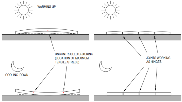
Figure 3. Schematic diagram of slab curling and warping (Adapted from EUPAVE ).
Concrete slabs are prone warping or curling when exposed to temperature differentials across their thickness- either positive or negative. In the case of uniform temperature change, the slab will tend to expand or contract as a whole. However, these movements are restrained by the frictional resistance at the interface between the slab and the subbase, as well as by the self-weight of the slab. In the absence of crack control measures- such as joints or reinforcement- these restrains can induce tensile stresses that may lead to cracking. The concept of thermal curling and warping in concrete slab is illustrated in Figure 3.
In the case of short slab resting on a smooth, planar subgrade with minimum restrain, the stresses induced by uniform thermal expansion can be considered negligible. Similarly, restraint stresses arising from contraction or drying shrinkage are generally insignificant. Furthermore, thermal curling stresses in short slabs tend to be relatively low compared to flexural stresses induced by traffic loading. As a result, the influence of thermal and shrinkage-related stresses is often considered minimal in the analysis, and these factors are typically excluded from practical pavement design considerations .
4.2. Foundation Support
Due to their inherent rigidity, concrete pavements exhibit a high load-spreading capacity. When subjected to loading, the stress is distributed over a wide area, resulting in relatively low pressure on the underlying subgrade. This implies that, unlike flexible pavements, concrete pavements do not necessarily require high subgrade strength; rather they depend on uniform and consistent support conditions. An excessively stiff foundation may resist conforming to slab movements caused by environmental factors such as thermal curling or warping, potentially leading to a loss of uniform support and resulting in increased stress concentrations. Therefore, the foundation system must achieve an appropriate balance between strength and flexibility to ensure long-term pavement performance. Studies have shown that low strength but uniform support soils often outperform higher strength soils that exhibit variability .
The foundation must possess sufficient strength to accommodate the anticipated construction traffic during the early stages of pavement development. The supporting strength of the foundation beneath the concrete slab is typically quantified by using Westergaard’s modulus of subgrade reaction or K-value , and is expressed in MPa/m. The K-value can be directly measured in the field using a plate load test or estimated based on empirical correlations between soil classification and bearing capacity values. Practical experience and research have shown that the concrete pavement thickness is relatively insensitive to moderate variations in K-values, particularly in lightly and moderately trafficked pavement applications . This relationship is illustrated in Figure 4. However, it is important to note that K-value is significantly influenced by factors such as moisture content, seasonal fluctuations, and geographical location.
Generally, it is more cost-effective to adjust other design parameters- such as increasing slab thickness, using higher grade concrete, improving edge support, or considering various other factors- rather than over-designing the subbase layer to achieve a higher composite K-value. As shown in Figure 4, increasing the K-value from 60 MPa/m to 180 MPa/m results in only a modest reduction of approximately 13% in the required concrete slab thickness.
Overall, composite K-value or CBR increases with the addition of subbase layer, a phenomenon referred to as the effective CBR in Austroads . The increase in effective subgrade strength due to the provision of bound subbase for design subgrade CBR ranging from 2% to 35% is provided in Austroads Figure 9.1 (not included in this manuscript). The effective subgrade CBR value is dependent on the degree of support provided by the underlying layers and it is recommended to adopt a maximum modulus ratio of granular subbase to subgrade soil of 5.0 as suggested by Heukelom and Klomp , in order to achieve a balance pavement structure. Austroads does not provide specific guidelines for multi-layered subgrades and the bound subbase thickness is limited to maximum 150 mm for a cost-effective design. In contract, PCA provides prescriptive K-values for both unbound and bound subbases with thickness ranges from 100 mm to 300 mm for unbound materials and 100 mm to 250 mm for bound materials, over subgrade with K-values up to 70 MPa/m.
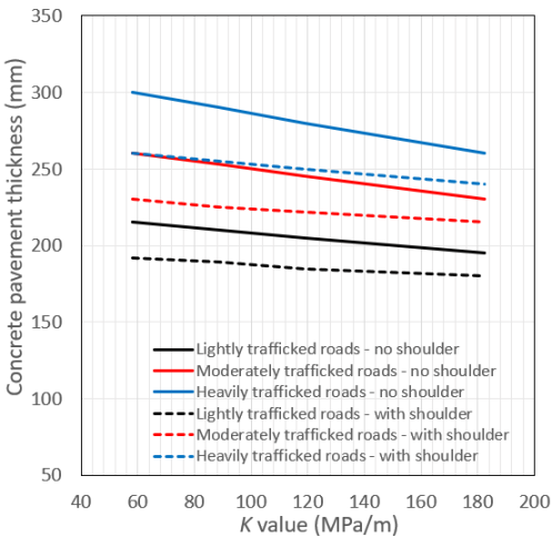
Figure 4. JPCP K-values for typical lightly (8×10³ ESA), moderately (2×10⁶ ESA) and heavily (1×10⁷ ESA) trafficked roads.
4.3. Subbase Layer
The subbase layer serves several key functions in concrete pavement design, including uniform bearing support, increase in foundation CBR, and provision for sufficient resistance to erosion of subbase material under traffic loading and environmental effects. The subbase layer increases the composite strength of the foundation support and is considered a critical layer. In lightly trafficked areas where erosion is generally not a predominant distress mode, unbound granular materials are commonly used in subbase layer. To minimise the risk of pumping, these materials should typically contain no more than 15% fines passing 75 μm sieve. In contract, bound subbases offer higher stiffness (i.e., higher K-values), more uniform support, and enhanced resistance to erosion compared to unbound subbases. They also contribute to improved load transfer across pavement joints and providing a stable construction platform for the placement of concrete slabs. Common types of bound subbases, for in heavily trafficked areas, include cement-treated crushed rock (CTCR), dense graded asphalt, lean mix concrete (LMC) and roller compacted concrete. CTCR, in particular, is widely used in many countries and can be cost-effective due to its placement method, which is similar to that of unbound granular subbase materials.
Australasian experience indicates that LMC subbases perform effectively when used in conjunction with undowelled PCP bases . They are typically constructed as mass concrete without transverse joints and therefore expected to develop uncontrolled cracking. The design approach aims to mitigate issues associated with excessive stiffness and the resultant high curling and warping stresses. It seeks to promote a network of closely spaced, narrow cracks that maintain adequate load transfer, particularly when used with an interlayer debonding system to prevent reflective cracking in the overlying concrete pavement. To ensure this, the 28-day compressive strength and shrinkage of LMC are limited to 5 MPa and 450 microstrain respectively. Austroads recommend selecting the minimum required subbase type based on anticipated design traffic levels. In Australia, LMC is predominantly used in heavy-duty pavements, whereas its use is less common internationally. In the US, for example, the preferred option for PCP is an unstabilised subbase with dowelled transverse joint . CTCR subbases are more widely used in European countries such as Belgium and Germany .
4.4. Concrete Shoulders
Field studies conducted by the PCA revealed that the outer wheel paths of trucks are typically located approximately 600 mm from the outer edge of the traffic lane, with around 6% of all axle wheel paths positioned near the pavement edge. Building upon these findings, Zollinger and Barenberg developed a stress analysis procedure that accounted for this edge loading condition by introducing an equivalent edge-stress factor for the 6% of the truck wheels that travel near the edge, while also incorporating the truck wander factor. This insight led to the use of concrete shoulder, which enables the pavement to be designed primarily for interior loading conditions, thereby resulting in a thinner slab thickness. Austroads recommend the use of 1.5 m tied concrete shoulder or an integrally cast concrete kerb and channel to enhance pavement performance. This design approach has demonstrated satisfactory performance in the field. Alternatively, the use of a widened outer lane- commonly used in Europe, particularly in France- has been suggested . Figure 4 presents a case study comparing JPCP with and without concrete shoulders, showing an average reduction of slab thickness by approximately 12% when shoulders are used.
4.5. Stress Ratio
Stress ratio offers a quantitative approach to determine the allowable stresses in concrete pavements. It is defined as the allowable flexural stress divided by the modulus of rupture (28-day characteristic concrete flexural strength). In essence, stress ratio is the inverse of the safety factor and can be expressed as either stress ratio = stress/strength or, conversely, safety factor = strength/stress. In concrete pavements, rupture typically occurs in flexure rather than in compression, particularly under loading conditions approaching the limit of structural capacity. This implies that cracking may initiate at any location within the pavement where tensile stresses exceed the concrete's flexural strength, underscoring the importance of accurately evaluating stress ratios in pavement design.
Numerous published studies have established the relationship between allowable number of load repetitions and stress ratios. These findings have been compiled and illustrated in Figure 5, which compares various concrete fatigue models proposed by researchers and agencies for use in concrete pavement design. As shown in the figure, lower stress ratios correspond to a higher number of load repetitions the slab can withstand before cracking occurs. Notably, the layered elastic model proposed by Sale and Hutchison represents a particularly conservative interpretation of the fatigue relationship compared to other models. The fatigue models proposed by the PCA and ACI are among the most widely adopted and demonstrate both reasonable consistently and a relatively conservative approach. Other curves, shown in Figure 5 are derived from a combination of analytical modelling, laboratory testing and field data. It is important to note that the fatigue relationships derived from AASHTO Road Test account for pavement damage caused by both concrete fatigue and erosion distress . Erosion distress tends to be the dominant failure mechanism in heavily trafficked pavements, such as highways. In conclusion, the considerable variation observed in the relationships between stress ratio and number of allowable load repetitions- coupled with the limited availability of comprehensive fatigue data- underscores the need for further research on the fatigue characteristics of JPCP.
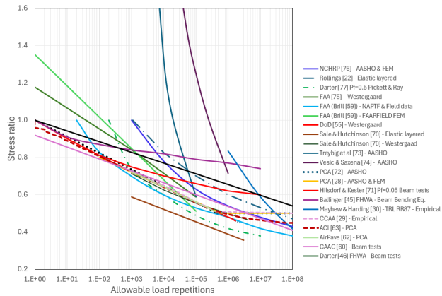
Figure 5. Fatigue curves for concrete pavement.
In the design methodologies proposed by PCA and CCAA , a design stress ratio of 0.50 is associated with an unlimited number of load repetitions, effectively representing the most conservative design case, effectively representing greatest pavement thickness. When a stress ratio of greater than 0.50 is used, fatigue analysis is employed to estimate the proportion of pavement life consumed by each design vehicle. The PCA method calculates pavement stresses using Westergaard’s interior loading analytical model and incorporates a safety factor ranging from 1.5 to 2.0. This approach accounts for concrete flexural strength and adopts a conservative interpretation of laboratory-based fatigue data. In doing so, it implicitly considers the elevated stresses occurring at slab joints and other additional stresses induced by environmental effects, such as thermal gradients and subgrade variability.
4.6. Concrete Flexural Strength
The primary failure mode of concrete pavement is typically flexural cracking. As a result, the flexural strength- also known as modulus of rupture- is a critical design parameter that directly influences both the required pavement thickness and the overall structural performance. Accurately estimating the flexural strength is therefore essential. However, due to considerations of convenience, cost-efficiency, test reliability, and the availability of laboratory resources, compressive strength is frequently used as an indirect measure to monitor flexural strength .
Past research has established a range of empirical relationships between flexural strength (ff) and compressive strength (fc,) of concrete as summarised in Table 2. It is important to note that no single, universally applicable correlation exists between these two parameters. The actual relationship can vary considerably depending on several factors, including the types of aggregates, cement, water-to-cement ratio, and the overall mix proportions. A generalised form of the empirical relationship can be expressed as in Equation (12).
ff=μfc(12)
where μ is a multiplier to square root of compressive strength of concrete.
Table 2. Empirical relationships between flexural strength and compressive strength of plain concrete.

Standard

Country

Relationship

IRC-58

India

ff = 0.70 fc

ACI

USA

ff = 0.62 fc

NZS 3101

New Zealand

ff = 0.60 fc

Concrete Society

TR34

United Kingdom

ff = fctm (1.6 - h/1000) γm

BS-8110

United Kingdom

ff = 0.60 fc

AS 3600

Australia

ff = 0.60fc

Austroads

Australia

ff = 0.75 fc

TfNSW-R83

NSW, Australia

ff = 0.76 fc

DTMR-MRTS40

Queensland, Australia

ff = 0.76 fc

CCAA

Australia

ff = 0.70 fc

ACPA

USA

ff ≈ 0.75 fc

Britpave

UK

ff = 0.75 fc

Denote: ff = 28-day concrete compressive strength, fctm = mean value of axial tensile strength of concrete, h base thickness and γm = partial factor of safety for materials.
Table 2 shows that the variation in k values adopted by different agencies can exceed 26%, indicating a significant degree of inconsistency. As a result, reliance solely on the compressive strength tests may lead to potential inaccuracies that could adversely affect the design outcomes. To account for variability in concrete strength, it is a standard practice to use flexural strength value that is approximately 15% lower than the average, corresponding to mean minus one standard deviation. Austroads specifies the use of characteristic strength aligned with the 95th percentile whereas AS 3600 , which governs the design of concrete structures, is based on the average 28-day concrete strength. The difference between characteristic and average strength is typically 15%, suggesting that the use of coefficient k = 0.6 in AS 3600 is conservative. Therefore, for major projects, it is recommended to verify the applicability of this relationship through mix design trials to ensure reliability and accuracy in structural performance.
4.7. Modulus of Elasticity
Modulus of elasticity (Ec) is a critical design input parameter for concrete pavements. It reflects the stiffness of the concrete and significantly influences structural performance and thickness requirements. The value of Ec varies depending upon the several factors, including the type of aggregates used, aggregate-to-cement ratio, and the age of the concrete. In general, the elastic modulus increases with the increase in compressive strength, thereby affecting the design thickness necessary to accommodate anticipated loading conditions.
Although it is ideal to determine the elastic modulus through laboratory testings of specific concrete mixes and materials intended for use in the field, such data are often unavailable during the design phase. In practice, the values are supplied by relevant agencies or estimated using the correlations based on the concrete compressive strength (fc). Well established relationships between the modulus of elasticity and compressive strength of concrete for general applications are summarised in Table 3. It is important to assess the applicability of these empirical formulas within the context of the specific pavement design, especially when the pavement may be sensitive to variations from these empirical correlations. Additionally, for materials with the E values below 21,000 MPa- such as lean mix concrete or cement-bound subbase layers- linear elastic theory may not provide an accurate representation of the behaviour. These materials often exhibit linear and bi-modular responses, necessitating more advanced modelling approaches .
Table 3. Empirical relationships between modulus of elasticity and compressive strength of plain concrete.

Standard

Country

Relationship

IRC-58

India

Ec = 30000 MPa for ff = 4.5 MPa

IS 456

India

Ec = 5000 fc

ACI 318-19

USA

Ec = 4700 fc or Ec = wc1.5 0.043fc

ACI 363R-10

USA

Ec = 3320 fc + 6900 or Ec = 3.385 x 10⁻⁵ x wc2.55 fc0.315

NZS 3101

New Zealand

Ec = 4734 (fc + 6900)

EN 1992-1-1

Europe

Ec = 22(fc / 10)0.3

BS-8110

United Kingdom

Ec = 20000 + 0.2fc

BDHK

Hong Kong

Ec = 3.46fc + 3.21

AASHTO-LRFD

USA

Ec = 2500(fc)0.33 or Ec = 1820 fc

AS 3600

Australia

For fc ≤ 40MPa, Ec = (ρ1.5) x (0.043fc)

For fc > 40MPa, Ec = (ρ1.5) x (0.024fc + 0.12)

4.8. Radius of Relative Stiffness
Westergaard introduces the concept of radius of stiffness to characterise the relative stiffness of rigid pavement base and subgrade, which in turn influences the stress distribution within the concrete pavement under applied loads. The value is large for a stiff slab resting on a soft foundation and small for a flexible slab supported by a stiff foundation. The radius of relative stiffness (l) as defined by Westergaard, is expressed in linear dimension, as given in Equation (13).
l=Eh3121-ν2K0.25(13)
The Poisson’s ratio (ν) for the concrete typically ranges from 0.15 to 0.20, its influence on the value of l is minimal when applied to Equation (13). For soils that are softer and more compressible, with smaller K-values, the value of l tends to be higher. Additionally, the value of l increases as the thickness of the concrete slab (h) increases.
Under interior loading conditions, as analysed by Westergaard, the slab undergoes deflection as illustrated in Figure 6. The figure shows that the maximum tensile stresses occur at the top of the slab, approximately 2.5l from the load, while the point of contraflexure- where bending moment chances sign- occurs at the bottom of the slab directly beneath the load, at a distance of l. Friberg expanded Westergaard’s work, concluding that the effective length of the slab, where the maximum negative moment occurs, is 1.8l. This implies that the dowel bar immediately under the applied load bears the full load, decreasing to zero at distance of 1.8l. Subsequent research, including finite element analyses, revisited Friberg’s proposed effective length, determining it to be 1.0l . Beyond this distance, the shear stresses are minimal and can be considered negligible . In contrast, the maximum shear stress occurs directly beneath the load, indicating that this location experiences critical shear stress. Thus, the area of load influence is a function of l.
AirPave defines the load influence zone as 3l, asserting that the stress contribution beyond this distance is negligible, which is considered a conservative approach. The relationship between l and the zone of influence is depicted in Figure 6, where a single point load is applied internally over a small circular area on a large concrete pavement. As the load increases, the flexural stresses induced beneath the load will surpass the flexural strength of the concrete, causing the slab to yield and resulting in radial tension cracks at the bottom. This phenomenon triggers a redistribution of moments, significantly increasing the circumferential moment beyond l. Tensile cracking will initiate when the maximum circumferential moment exceeds the negative moment capacity of the slab, ultimately resulting in slab failure characterised by surface cracking.
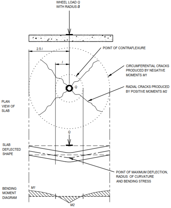
Figure 6. Radial, circumferential cracks and zone of influence in JPCP (Adapted from TR34 ).
4.9. Concrete Joint Spacing
Concrete volume changes throughout its lifespan due to chemical reactions affected by fluctuations in temperature and moisture, often resulting in uncontrolled cracking . To mitigate this, joints are strategically placed in concrete structures to control the location of anticipated natural cracks. The spacing of these joints is significantly influenced by local environmental conditions, the properties of the materials used, and the characteristics of the subgrade. Darter et al. provide recommendations for maximum joint spacing tailored to different climatic conditions, incorporating factors such as the modulus of subgrade reaction (K) and slab thickness (h). As a general guideline, environments with greater temperature variability warrant shorter joint spacing to better accommodate volumetric changes.
The primary principle in determining joint spacing is its relationship to slab thickness. Thinner slabs are more susceptible to curling stresses, necessitating shorter joint spacing to effectively control cracking. According to ACI , the slab length (in feet) should range from 2 to 2.5 times the slab thickness (in inches), with a maximum joint spacing of 5 m and an L/l ratio not exceeding 4.44. For JPCPs, joint should be closely spaced, ideally less than 25 to 30 times the base thickness . FHWA advises that joint spacing should not exceed 19 to 24 times the slab thickness to prevent uncontrolled cracking. Britpave recommends maximum transverse joint spacing of less than 24 times the base thickness, with a maximum spacing of 5 m for transverse joints and 4.5 m for longitudinal joints. The ACPA suggests that maximum transverse joint spacing of 24 times the base, with a maximum limit of 4.6 m. In specific applications such as roundabouts and bus lanes, EUPAVE permits increased slab thickness while restricting slab lengths to L ≤ 20h. Closely spaced joints are effective in controlling cracking by relieving shrinkage and thermal stresses, thereby reducing the necessity for reinforcement.
Using the maximum L/l ratio of 4.44, and assuming the concrete modulus of elasticity of 27,579 MPa and a Poisson’s ratio of 0.15, the relationships between slab thickness, slab length and K value has been plotted in Figure 7, which shows that the allowable joint spacing increases with greater slab thickness but decreases with an increasing K-value. Accordingly, Figure 7 is proposed as an alternative to the general ACI guideline discussed earlier.
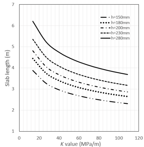
Figure 7. Relationships between slab length, pavement thickness and K value.
The second design guideline is that the geometry should be as close to square as possible. According to FHWA and ACPA , the aspect ratio of concrete slabs should not exceed 1.5 (i.e., L/W ≤ 1.5). However, AASHTO , RMS and FAA recommend a more stringent maximum aspect ratio of 1.25. For slabs where the aspect ratio exceeds 1.25, or for those with irregular geometries, it is recommended to provide a minimum of 0.05% reinforcement of the panel’s cross-sectional area in both directions. This reinforcement helps to tightly close uncontrolled cracks, thereby minimising the risk of infiltration of debris and improving long-term durability .
The third design guideline sets a definitive limit on the length of JPCP, specifying a predefined value. In some jurisdictions, joint spacing is restricted to between 5 to 7 m, depending on slab thickness . RMS guidelines a widely adopted guideline in Australia--recommend a minimum joint spacing of 3.4 m and a maximum of 4.2 m. This recommendation is grounded in observed field performance, where smaller panel sizes have demonstrated reduced susceptibility to cracking, thereby enhancing pavement longevity. A 2018 survey reported that 85% U.S. State Highway Agencies adopted a joint spacing of 4.6 m .
Furthermore, research has established an empirical relationship of L/l ratio. Ioannides et al. showed that this ratio can serve as a reliable indicator for the maximum allowable slab length. By comparing analytical results with finite element analyses, Ioannides et al. concluded that the minimum L/l ratios of 3.5, 5.0 and 4.0 are required to satisfy Westergaard’s assumptions for interior, edge and corner loading conditions, respectively. FHWA recommended a maximum L/l ratio of 5.0 when determining the joint spacing. In contract, the design guidelines by ACI limit L/l ratio to 4.44 and suggest that joint spacing should be reduced accordingly to accommodate increased curling stresses associated with stiffer subgrade. More recently, Brinks proposed an L/l ratio of 7.0 as an effective criterion for crack control and to mitigate the risk of uncontrolled cracking. Generally, L/l ratios of 7.0 and 5.0 are adopted for heavy-duty and light-duty pavements, respectively.
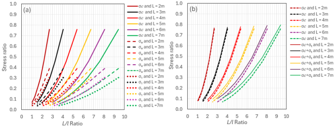
Figure 8. Stress ratio vs L/l ratio (a) for corner σ𝒸, edge σₑ and interior stresses σ₁ (b) for corner and thermal stresses σt.
To evaluate the relationships between stress ratio and L/l, the Westergaard method. The analysis assumes a concrete compressive strength of 40 MPa, the modulus of subgrade reaction of 100 MPa/m, and a Poisson’s ratio of 0.15. Slab thickness ranging from 150 mm to 550 mm and slab lengths from 2 m to 7 m are considered. A summary of the computational results is graphically presented in Figure 8a. The results indicate that the corner stresses are the highest, followed by edge stresses and interior stresses. This confirms that loading at the corners produces the most critical stresses in the pavement system. In addition to mechanical loading, thermal stresses are also evaluated for comparison with corner stresses. The thermal stresses are computed using the classical subgrade drag theory equations proposed by Bradbury and Darter . As shown in Figure 8b, thermal stresses are minimum for slabs with short joint spacings- specifically those under 7 m in length. This suggests that the thermal stresses are negligible in relatively short slabs, supporting their exclusion from designs in methodologies such as those proposed by the PCA and Austroads.
5. Conclusion
There is a shift in the design methods of Jointed Plain Concrete Pavement (JPCP) from purely empirical methods to mechanistic-empirical approaches. With the capability to model complex loading conditions through finite element methods and advanced testing techniques, the design process is moving towards mechanistic methods. It is now widely recognised that key input parameters play a crucial role in determining the performance of concrete pavements. To evaluate the performance of JPCP, the fatigue failure criterion is widely recognised and used globally. The rate of concrete pavement deterioration related to fatigue depends on various factors, including slab thickness, foundation support conditions, loading and environmental effects, tyre pressure, concrete properties, the presence or absence of shoulders, radius of relative stiffness, ratio of joint spacing to radius of relative stiffness and other key input parameters. Based on a review of literature, significant variations in stress ratios with allowable load repetitions have been observed, yet the available information remains limited, indicating a pressing need for further research on the fatigue criterion for JPCP. Additionally, erosion failure has been identified as another important damage model used by some agencies. The design methods and the performance failure criteria (and associated equations) developed by various agencies and researchers are valid only under specific conditions. As such, the performance failure criterion is inherently tied to the design methods, making it unsuitable for direct comparison with other methods in isolation.
The erosion distress prediction model developed by PCA is based on AASHTO road test, which primarily includes granular subbase materials as well as a number of faulting studies . Since 1984, both Australian and international research have contributed valuable findings on the characterization of the erodibility of subbase materials, which have yet to be included in Austroads and PCA design procedures. The appropriate incorporation of these recent research findings could lead to more optimized designs, potentially reducing the thickness while offering cost savings and sustainability benefits. The PCA’s 1992 faulting models for aggregate-interlock and dowelled joints are based on empirical field data from JPCP long term pavement performance test program. However, the linear regression techniques used to derive the faulting failure equation resulted in an R2 value of around 0.7, which is considered statistically not strong and has limited adoption in practice. The integration of a more robust faulting damage model would require significant advancements, indicating a clear need for further research in this area.
It is recommended that further research work is undertaken to develop a more robust faulting damage model to enhance the prediction of JPCP performance.
Notation
Unless noted otherwise the following notation will apply.

a

Radius of load footprint

b

Equivalent radius = (1.6a2 +h2)0.25 – 0.675h for a < 1.724h; b = a for a >1.724h

c

Side length of square load.

C

Dimensionless coefficient independent of Q/h2 and is a function of a/l

Ec

Modulus of elasticity of concrete

fc

Concrete compressive strengths fc

ff

Concrete flexural strength

F

Failed bays at the end of life is 30%

F1

Axle group type

F2

Adjustment for slab edge effects 0.06 to 0.94

F3

Erosion factor

F4

Load adjustment for erosion due to axle group

h

Concrete slab thickness

k

Dimensionless coefficient and is the function of ff

K

Modulus of subgrade reaction

l

Relative stiffness radius

L

Concrete slab length

LSF

Load safety factor

M

Equivalent modulus of a uniform foundation (MPa)

Nf, Ne

Allowable load repetitions for fatigue and erosion failure respectively

Ni,j,k,…

Allowable number of load applications at conditions i, j, k, l, m, n,

Q

Total applied load

p

Rate of work or power

P

Axle group load (kN)

r

A measure of loading range (ratio of flexural stress at minimum load to maximum load)

R

Design reliability

Se

Equivalent concrete stress (MPa)

SR

Stress ratio

W

Concrete slab width

σ1, σe, σc

Maximum interior, edge and corner stresses in the slab respectively

σi,j,k, …

Applied stress at condition i, j, k, l, m, n,

μ

Poisson’s ratio

Δ

Slab deflection

Abbreviations

JPCP

Jointed Plain Concrete Pavement

PCA

Portland Cement Association

ICT

Intermodal Container Terminals

AASHTO

American Association of State Highway and Transportation Officials

CCAA

Cement Concrete Association Australia

TRL RR

Transport Research Laboratory Research Report

TR

Technical Report

IRC

Indian Road Congress

CDF

Cumulative Damage Factor

NCHRP

National Cooperative Highway Research Program

MEPDG

Mechanistic-Empirical Pavement Design Guide

FHWA

Federal Highway Administration

PCC

Precast Concrete

AASHO

American Association of State Highway Officials

PSI

Pavement Serviceability Index

ELM

Elastic Layered Method

USACE

United Staes Corps of Engineers

DA&AF

Departments of the Army and the Air Force

SCI

Structural Condition Index

ACI

American Concrete Institute

DoD

Department of Defence

ARA

Applied Research Associates

FAA

Federal Aviation Administration

FAAFIELD

FAA Rigid and Flexible Interactive Elastic Layer

CAAC

Civil Aviation Administration of China

CBR

California Bearing Ratio

ESA

Equivalent Standard Axle

CTCR

Cement Treated Crushed Rock

LMC

Lean Mix Concrete

TfNSW

Transport for New South Wales

DTMR

Department of Transport and Main Roads

AS

Australian Standards

IS

India Standards

NZS

New Zealand Standards

EN

Eurocodes

BS

British Standards

BDHK

Building Department Hong Kong

LRFD

Load and Resistance Factor Design

ACPA

American Concrete Pavement Association

RMS

Roads & Maritime Services

Author Contributions
Boon Tiong Chua: Conceptualization, Data curation, Formal Analysis, Investigation, Methodology, Resources, Software, Validation, Writing – original draft, Writing – review & editing
Kali Prasad Nepal: Supervision, Validation, Writing – review & editing
Conflicts of Interest
The authors declare no conflicts of interest.
References
[1] EUPAVE, Guide for design of jointed plain concrete pavements. European Concrete Paving Association, Brussels, 2020.
[2] IRC:58-2015, Guidelines for the design of plain jointed rigid pavements for highways (Fourth Revision), Indian Roads Congress, New Delhi, India, 2015.
[3] Austroads, Guide to pavement technology Part 2: Pavement Structural Design. Austroads Publication No. AGPT02-17, Sydney, NSW, 2017, ISBN: 978-1-925854-69-5.
[4] ACPA, Design of concrete pavement for streets and roads, Concrete information, American Concrete Pavement Association, Skokie, Ill., USA, 2006.
[5] Ray, G. K., History and development of concrete pavement design, Journal of the Highway Division, 90(1). American Society of Civil Engineers, 1964,
[6] Westergaard, H. M., Analysis of stresses in concrete pavement due to variation of temperature, Highway Research Board, 1926, 6, 201-215, USA.
[7] Westergaard, H. M., Stresses in concrete pavements computed by theoretical analysis, Public Roads, 1926, 7(2), 25-35, USA.
[8] Westergaard, H. M., New formulas for stresses in concrete pavements of airfields, Transactions, 1948, 113, American Society of Civil Engineers, New York, USA.
[9] Ioannides, M. R., Thompson, M. R., Barenberg, E. J., Westergaard solutions reconsidered, Transportation Record Board 1043, Washington, DC., USA, 1985.
[10] Kelley, E. F., Application of the results of research to the structural design of concrete pavement, Public Roads, 20(5), USA, 1939.
[11] Teller, L. W., Sutherland, E. C., The structural design of concrete pavements, Part 5:00 An experimental study of the Westergaard Analysis of the stress condition in concrete pavement slabs of uniform thickness, Public Roads, 23(8), USA, 1943.
[12] Goldbeck, A. T., Thickness of concrete slabs, Public Roads, 1(12), USA, 1919.
[13] Older, C., Highway Research in Illinois, ASCE Transactions, 87, USA, 1924.
[14] Bradbury, R. D., Reinforced concrete pavements, Wire Reinforcement Institute, Washington, D. C., USA, 1938.
[15] Spangler, M. G., Stresses in corner region of concrete pavements, Bulletin 157 Engineering Experiment Station, Iowa State College, Ames, USA, 1942.
[16] Pickett, G., Concrete pavement design, Appendix III: A study of stresses in the corner region of concrete pavement slabs under large concrete loads, Portland Cement Association, Stokie, Ill., USA, 1946.
[17] Olita, S., Diomedi, M., Ciampa, D., Alternative formula for rigid pavement stress calculation in corner load conditions, The Baltic Journal of Road and Bridge Engineering, 2020, 15(5), 59-79, eISSN 1822-4288,
[18] Pickett, G., Ray, G., Influence charts for concrete pavements, Transactions, 116, American Society of Civil Engineers, New York, USA 1951.
[19] Kreger, W. C., Computerised aircraft ground flotation analysis edge loaded rigid pavement, EER-FW-572, General Dynamics, FT. Worth, Texas, USA, 1967.
[20] Eberhardt, A. C., An analysis of Pickett’s solution to Westergaard’s equation for rigid pavements, Department of the Army Construction Engineering Research Laboratory, Champaign, Illinois, USA, 1973.
[21] Witczak, M. W., Uzan, J., Johnson, M., Development of probabilistic rigid pavement design methodologies for military airfields, Technical report GL-83-18, US Army Engineer Waterways Experiment Station, Vicksburg, Miss., USA, 1983.
[22] Rollings, R. S., Design of rigid overlays for aircraft pavements, PhD Dissertation, University of Maryland, USA, 1987.
[23] Jiang, Y. J., Tayabji, S. D., Wu, C. L., Mechanistic evaluation of test data from LTPP jointed concrete pavement test sections, Final report FHWA-RD-98-094, Federal Highway Administration, USA, 1998.
[24] Nejad, F. M., Non liner finite element analysis of reinforced and unreinforced pavements, IJE Transition, 2004, 17(3), 213-226.
[25] AASHTO, AASHTO guide to design of pavement structures, American Association of State Highway and Transportation Officials, Washington, DC., USA, 1993, ISBN: 1560510552.
[26] AASHO, Interim guide for design of pavement structures, American Association of State Highway Officials, Washington, DC., USA, 1972.
[27] Van, C. V., Mcmullough, B. F., Vallerga, B. A., Hicks, R. G., Evaluation of AASHO interim guides for design of pavement structures, NCHRP Report 128, American Association of State Highway Officials, Washington, DC., USA, 1972,
[28] Portland Cement Association (PCA), Thickness design for concrete highway and street pavements, EB109.01P, Skokie, Ill., USA, 1984.
[29] Cement Concrete & Aggregate Australia (CCAA), Guide to industrial floors and pavements – Design, construction and specification, Cement Concrete & Aggregate Australia, 2009, ISBN 978-1-877023-26-2.
[30] Mayhew, H. C., Harding, H. M., Thickness design of concrete roads, Research Report 87, Transport Research Laboratory, Crowthorne, UK, 1987, ISSN: 0266-5247.
[31] Concrete Society, Technical Report 66, External in-situ concrete pavement. Camberley, Surrey, UK, 2007, ISBN: 1-904482-37-6.
[32] ACPA, Design of concrete pavement for city streets, Concrete information, American Concrete Pavement Association, Skokie, Ill., USA, 1992.
[33] Hong Kong Highway Department, Guidance notes on pavement design for carriageway construction, Research & Development Division, RD/GN/042, Hong Kong, 2013.
[34] Roesler, J., Desantis, J., Mechanistic-Empirical design methods for concrete pavement solutions, National Concrete Consortium, National Concrete Pavement Technology Centre, USA, 2022.
[35] BRITPAVE, Concrete hardstand design handbook – Design guidance (3rd Edition). Berkshire, UK, 2023.
[36] AUSTROADS, Guide to pavement technology Part 2: Pavement Structural Design, Austroads Publication No. AGPT02-24, Sydney, NSW, Australia, 2024, ISBN: 978-1-922700-94-0.
[37] IRC: SP: 62-2014, Guidelines for design and construction of cement concrete pavements for low volume roads (First Revision), Indian Roads Congress, New Delhi, India, 2014.
[38] Miner, M. A., Cumulative damage in fatigue, Journal of Applied Mechanics, 1945, 12, 149–164.
[39] Wu, C. L., Mack, J. W. Okamoto, P. A., Parkard, R. G., Prediction of faulting of joints in concrete pavements, Proceedings of the 5th International Conference on Concrete Pavement Design and Rehabilitation, Purdue University, Indiana, USA, 1993.
[40] NCHRP, Guide for mechanistic-empirical design of new and rehabilitated pavement structures, Final report (NCHRP Project 1-37A), Transportation Research Board, National Cooperative Highway Research Program, Washington, DC., USA, 2004.
[41] Jameson, G., Technical basis of Austroads Guide to Pavement Technology - Part 2: Pavement Structural Design, Research report ARR384, ARRB Group, Vermont South, Vic., Australia, 2013.
[42] Wijk, I. V., Review of the erosion criteria for bound subbases in the Australian rigid pavement design procedure, 6th Concrete Pavements Conference, Australian Society of Concrete Pavement, NSW, Australia, 2021.
[43] Shahi, P. B., Pavement design guidelines (Rigid Pavement), Department of Roads, Nepal, 2021.
[44] Murdock, J. W., Kesler, C. E., Effect of range of stress on fatigue strength of plain concrete beams, Proceedings, American Concrete Institute, 1958, 55, 221-231,
[45] Ballinger, C. A., Cumulative fatigue damage characteristics of plain concrete, Highway Research Record No. 370, Highway Research Board, Dept. of Transportation, Federal Highway Admin., USA, 1972.
[46] Darter, M. I., Design of zero-maintenance plain jointed concrete pavement, Volume I – Development of design procedure, Report FHWA-RD-77-111, FHWA, USA, 1977.
[47] Nordby, G. M., Fatigue of concrete – A review of research. Proceedings, American Concrete Institute, 1959, 55, 191-220, DOI: 10.14359/11349.
[48] Raithby, K. D., Galloway, J. W., Effects of moisture condition, age and rate of loading on fatigue of plain concrete, SP-41, American Concrete Institute, USA, 1974.
[49] Packard, R. G., Tayabji, S. D., New PCA thickness design procedure for concrete highway and street pavements, Proceedings of the 3rd International Conference on Concrete Pavement Design and Rehabilitation, Purdue University, West Latayette, IN., USA, 1985.
[50] Huang, Y. H., Pavement analysis and design. Prentice-Hall Inc., USA, 1993, ISBN: 9780136552758.
[51] Chou, Y. T., Development of failure criteria of rigid pavement thickness requirements for military roads and streets elastic layered method, Department of Army, Corps of Engineers, Vicksburg, Mississippi, USA, 1989.
[52] DA&AF., Pavement design for roads, streets and open storage areas, elastic layered method, TM 5-822-13/AFJMAN 32-1018, Departments of the Army and the Air Force, Washington, DC., USA, 1994.
[53] ACI 215R-74, Considerations for design of concrete structures subjected to fatigue loading, American Concrete Institute Committee 215, Farmington Hills, MI, USA, 1997.
[54] Lee, Y-H., Carpenter, S. H., PCAWIN Program for jointed concrete pavement design. Tamkang Journal of Science and Engineering, University Tamkang, 4(4), 293-300. Taipei, Taiwan, 2001,
[55] DoD, Unified facilities criteria – Pavement design for airfields, UFC 3-260-02, Department of Defence, U.S. Army Corps of Engineers, Washington, DC., USA, 2001.
[56] Applied Research Associates (ARA), Guide for mechanistic-empirical design of new and rehabilitated pavement structures, Final Report, NCHRP Project 1-37A, Transportation Research Board, Washington, DC., USA, 2004.
[57] AASHTO, Mechanistic-Empirical pavement design guide, A manual of Practice, (Interim Edition), American Association of State Highway and Transportation Officials, Washington, DC., USA, 2008, ISBN: 978-1-56051-423-7.
[58] ACI 363R-10, Report on high strength concrete, American Concrete Institute, USA, 2010, ISBN: 978-0-87031-254-0.
[59] Brill, D. R., Calibration of FAARFIELD rigid pavement design procedure, Report No. DOT/FAA/AR-09/57, U.S. Department of Transportation Federal Aviation Administration, NJ., USA, 2010.
[60] CAAC, Specifications for airport cement concrete pavement design, Civil Aviation Administration of China, Beijing, China, 2010.
[61] Roesler, J., Bordelon, A., Brand, A. S., Amirkhanian, A., Fiber reinforced concrete pavement overlays: Technical overview, Report No. In trans Project 15-532, National Concrete Pavement Technology Centre, Iowa State University, IA, USA, 2019.
[62] AIRPAVE, AirPave guide, American Concrete Pavement Association, USA, 2024,
[63] ACI 360R-10, Guide to design of slabs-on-ground, Report by ACI Committee 360 American Concrete Pavement Association, USA, 2010, ISBN: 978-0-87031-371-4.
[64] ACPA, Subgrades and subbases for concrete pavements, TB011P, American Concrete Pavement Association, Skokie, Ill., USA, 1995.
[65] ACPA, Subgrades and subbases for concrete pavements, American Concrete Pavement Association, Skokie, Ill., USA, 2007, ISBN: 978-0-9800251-0-1.
[66] Heukelom, W., Klomp, A., Dynamic testing as a means of controlling pavements during and after construction, International Conference on the Structural Design of Asphalt Pavements, University of Michigan, USA, 1962.
[67] Buckingham-Jones, T., Hayde, C., A subbase odyssey, 6th Concrete pavements conference, NSW, Australia, 2021.
[68] Zollinger, D. G., Barenberg, E. J., A mechanistic based design procedure for jointed concrete pavements, 4th International Conference on Concrete Pavement Design and Rehabilitation, 75-97, West Lafayette, Indiana, USA, 1989.
[69] AUSTROADS, Technical basis of Austroads Guide to Pavement Technology Part 2: Pavement Structural Design, Austroads Publication No. AP-T98/08, Australia, 2008, ISBN 978-1-921329-72-2.
[70] Sale, J., Hutchinson, R., Development of rigid pavement design criteria for military airfields, Journal of the Air Transport Division, 83, AT3, American Society of Civil Engineers, New York, USA, 1959.
[71] Hilsdorf, H. K., Kesler, C. E., Fatigue strength of concrete under varying flexural stresses, Proceedings, American Concrete Institute, 63, 1059-1976, USA, 1966.
[72] Portland Cement Association (PCA), Thickness design of concrete pavements, Portland Cement Association, Skokie, Ill., USA, 1966, ISBN: 893121193
[73] Treybig, H., Mccullough, B. F., Smith, P., Quintus, H. V., Overlay design and reflection cracking analysis for rigid pavements: Vol. 1, Development of new design criteria, Report No. FHWA-RD-77-6, Vol. 1, Federal Highway Administration, Washington, DC., USA, 1977.
[74] Vesic, A. S., Saxena, S. K., Analysis of structural behaviour of road test rigid pavements, Highway Research Board, Washington, DC., USA, 1969.
[75] FAA, Advisory Circular AC 150.5320-6D, Airport pavement design and evaluation Federal Aviation Administration, Office of Airport Safety and Standards, USA, 1995.
[76] NCHRP, Calibrated mechanistic structural analysis procedures for pavements, Volume I – Final report (NCHRP Project 1-26), Transportation Research Board, National Cooperative Highway Research Program, Washington, DC., USA, 1992.
[77] Darter, M. I., Concrete slab vs beam fatigue model, In Proceedings of the Second Workshop on the theoretical design of concrete pavements, Siguenza, Spain, 1990.
[78] ACI 228.2R, Guide for selecting proportions for no-slump concrete, American Concrete Institute Committee 211.3R-02, Farmington Hills, MI, USA, 1998.
[79] NZS 3101.1, Concrete structures standard – Part 1: The design of concrete structures. Standards New Zealand, 2006.
[80] Concrete Society, Technical Report 34, Concrete industrial ground floors – A guide to design and construction (Fourth Edition), Camberley, Surrey, UK, 2016, ISBN: 978-1-904482-77-2.
[81] BS 8110-1, Structural use of concrete – Part 1: Code of practice for design and construction, British Standard, United Kingdom, 1997.
[82] AS 3600, Concrete structures, Standards Australia, 2018.
[83] Transport for NSW (TfNSW), QA Specification R83 – Concrete pavement base, New South Wales, Australia, 2021.
[84] Department of Transport and Main Roads Queensland (DTMR), Technical specification – MRTS40 Concrete pavement base, Queensland, Australia, 2018.
[85] ACPA, Concrete information – Design of concrete pavement for streets and roads, American Concrete Pavement Association, USA, 2016.
[86] IS 456, Plain and reinforced concrete code of practice (Fourth Revision), Bureau of India Standards, New Delhi, India, 2000.
[87] ACI 318-19, Building code requirements for structural concrete and commentary, American Concrete Institute, USA, 2022, ISBN: 978-1-64195-056-5.
[88] EN 1992-1-1, Eurocode 2: Design of concrete structures – Part 1-1: General rules an rules for buildings, 2004.
[89] BDHK, Code of Practice for structural use of concrete, Buildings Department, Hong Kong, 2020.
[90] AASHTO LRFD, Bridge design specification (8th Edition), American Association of State Highway and Transportation Officials, Washington, DC., USA, 2017, ISBN: 978-1-56051-654-5.
[91] Friberg, B. F., Design of dowels in transverse joints of concrete pavements, Transactions, Vol. 105, American Society of Civil Engineers, New York, NY, USA, 1940.
[92] Tabatabaie, A. M., Barenburg, E. J., Smith, R. E., Longitudinal joint systems in slip formed rigid pavements, Vol. ll-Analysis of load transfer systems for concrete pavements, Report No. DOT/FAA.RD-79/4, Federal Aviation Administration, USA, 1979.
[93] Vandenbossche, J. M., An analysis of the longitudinal reinforcement in a jointed reinforced concrete pavement, MSc. Thesis, Michigan State University, USA, 1995.
[94] Snyder, M. B., Dowel load transfer systems for full-depth repairs of jointed Portland cement concrete pavements, Ph.D. Thesis, University of Illinois, Urbana, IL, USA, 1989.
[95] Darter, M. I., Von Quintus, H., Jiang, Y. J., Owusu-Antwi, E. B., Killingsworth, B. M., Catalogue of recommended pavement design features, Final report, NCHRP Project 1-32, Transportation Research Board, Washington, DC., USA, 1997.
[96] ACI 325.12R-02, Guide for design of jointed concrete pavements for streets and local roads, Report by ACI Committee 325 American Concrete Pavement Association, USA, 2002.
[97] FHWA, Concrete pavement joints, Federal Highway Administration, Washington, DC, USA, 2019.
[98] ACPA, Web Application “ Max joint spacing”, 2019,
[99] Road & Maritime Services (RMS), Pavement standard drawings, Rigid pavement: Standard details – Construction, Volume CP – Plain Concrete Pavement, NSW, Australia, 2016.
[100] FAA, Advisory Circular AC 150/5320-6G, Airport pavement design and evaluation. U.S. Department of Transportation, Federal Aviation Administration, USA, 2021.
[101] Kaya, O., Comprehensive evaluation of transverse joint spacing in jointed plain concrete pavement, Journal of Construction, 2022, 21(3), 618-630,
[102] FHWA, Concrete pavement joints, Technical advisory T 5040.30, Federal Highway Administration, Washington, DC, USA, 1990.
[103] Brink, A-C., Concrete pavements in the public domain, ASCP2023 – 7th Concrete Pavements Conference, Australian Society of Concrete Pavement, Wollongong, Australia, 2023.
Cite This Article
  • APA Style

    Chua, B. T., Nepal, K. P. (2025). A Review of the Performance Criteria and Key Design Input Parameters for Jointed Plain Concrete Pavements. American Journal of Civil Engineering, 13(3), 165-184. https://doi.org/10.11648/j.ajce.20251303.15

    Copy | Download

    ACS Style

    Chua, B. T.; Nepal, K. P. A Review of the Performance Criteria and Key Design Input Parameters for Jointed Plain Concrete Pavements. Am. J. Civ. Eng. 2025, 13(3), 165-184. doi: 10.11648/j.ajce.20251303.15

    Copy | Download

    AMA Style

    Chua BT, Nepal KP. A Review of the Performance Criteria and Key Design Input Parameters for Jointed Plain Concrete Pavements. Am J Civ Eng. 2025;13(3):165-184. doi: 10.11648/j.ajce.20251303.15

    Copy | Download

  • @article{10.11648/j.ajce.20251303.15,
      author = {Boon Tiong Chua and Kali Prasad Nepal},
      title = {A Review of the Performance Criteria and Key Design Input Parameters for Jointed Plain Concrete Pavements
    },
      journal = {American Journal of Civil Engineering},
      volume = {13},
      number = {3},
      pages = {165-184},
      doi = {10.11648/j.ajce.20251303.15},
      url = {https://doi.org/10.11648/j.ajce.20251303.15},
      eprint = {https://article.sciencepublishinggroup.com/pdf/10.11648.j.ajce.20251303.15},
      abstract = {The design of Jointed Plain Concrete Pavement (JPCP) is typically carried out using the total fatigue and/or erosion damage models, based on the requirements outlined in the design brief or the specific practical conditions. The fatigue failure and erosion damage models criteria are widely recognised and used globally to evaluate the performance of JPCP. The performance failure criterion is inherently tied to the design methods, making it unsuitable for direct comparison with other methods in isolation. But the most widely used the mechanistic-empirical design procedure for JPCP is heavily reliant on the calibration of these damage models, which illustrate the relationship between stress ratio (the allowable flexural stress divided by the modulus of rupture) and the allowable number of load repetitions for a specific axle load. The induced flexural stress in the pavement is influenced by numerous factors, including foundation support conditions, axle loads, load locations (interior, edge and corner), design traffic loading, tyre pressure, concrete properties, slab size (with and without concrete shoulders), the ratio of joint spacing to radius of relative stiffness, and other key design parameters. This paper presents an extensive literature review of these key design factors that influence the design of JPCP, with the aim of enhancing the understanding of pavement behaviour and optimising pavement performance for cost-effective designs. The literature review also reveals that erosion distress prediction model developed by Portland Cement Association is based primarily on granular subbase materials which is dated and the benefit of using as non-erodible subbase materials is not incorporated in the performance assessment. Furthermore, the integration of a more robust faulting damage model would require significant advancements, indicating a clear need for further research in this area. The analysis further reveals that the thickness of concrete pavement is relatively insensitive to modest changes in the modulus of subgrade reaction (K). Additionally, it shows that the allowable joint spacing increases with greater slab thickness but decreases as the K-value rises. The average reduction in slab thickness is found to be approximately 12% when concrete shoulders are used in the design. The findings underscore the importance of integrating various design aspects of JPCP, rather than treating them as a series of isolated activities or materials, in order achieve optimal pavement performance.
    },
     year = {2025}
    }
    

    Copy | Download

  • TY  - JOUR
    T1  - A Review of the Performance Criteria and Key Design Input Parameters for Jointed Plain Concrete Pavements
    
    AU  - Boon Tiong Chua
    AU  - Kali Prasad Nepal
    Y1  - 2025/06/30
    PY  - 2025
    N1  - https://doi.org/10.11648/j.ajce.20251303.15
    DO  - 10.11648/j.ajce.20251303.15
    T2  - American Journal of Civil Engineering
    JF  - American Journal of Civil Engineering
    JO  - American Journal of Civil Engineering
    SP  - 165
    EP  - 184
    PB  - Science Publishing Group
    SN  - 2330-8737
    UR  - https://doi.org/10.11648/j.ajce.20251303.15
    AB  - The design of Jointed Plain Concrete Pavement (JPCP) is typically carried out using the total fatigue and/or erosion damage models, based on the requirements outlined in the design brief or the specific practical conditions. The fatigue failure and erosion damage models criteria are widely recognised and used globally to evaluate the performance of JPCP. The performance failure criterion is inherently tied to the design methods, making it unsuitable for direct comparison with other methods in isolation. But the most widely used the mechanistic-empirical design procedure for JPCP is heavily reliant on the calibration of these damage models, which illustrate the relationship between stress ratio (the allowable flexural stress divided by the modulus of rupture) and the allowable number of load repetitions for a specific axle load. The induced flexural stress in the pavement is influenced by numerous factors, including foundation support conditions, axle loads, load locations (interior, edge and corner), design traffic loading, tyre pressure, concrete properties, slab size (with and without concrete shoulders), the ratio of joint spacing to radius of relative stiffness, and other key design parameters. This paper presents an extensive literature review of these key design factors that influence the design of JPCP, with the aim of enhancing the understanding of pavement behaviour and optimising pavement performance for cost-effective designs. The literature review also reveals that erosion distress prediction model developed by Portland Cement Association is based primarily on granular subbase materials which is dated and the benefit of using as non-erodible subbase materials is not incorporated in the performance assessment. Furthermore, the integration of a more robust faulting damage model would require significant advancements, indicating a clear need for further research in this area. The analysis further reveals that the thickness of concrete pavement is relatively insensitive to modest changes in the modulus of subgrade reaction (K). Additionally, it shows that the allowable joint spacing increases with greater slab thickness but decreases as the K-value rises. The average reduction in slab thickness is found to be approximately 12% when concrete shoulders are used in the design. The findings underscore the importance of integrating various design aspects of JPCP, rather than treating them as a series of isolated activities or materials, in order achieve optimal pavement performance.
    
    VL  - 13
    IS  - 3
    ER  - 

    Copy | Download

Author Information
  • Abstract
  • Keywords
  • Document Sections

    1. 1. Introduction
    2. 2. Concrete Pavement Design Methods
    3. 3. Performance Criteria
    4. 4. Factors Affecting JPCP Design
    5. 5. Conclusion
    Show Full Outline
  • Notation
  • Abbreviations
  • Author Contributions
  • Conflicts of Interest
  • References
  • Cite This Article
  • Author Information